background image

Document Revision 1

Electra Elite IPK II

24

Standard View


8.0.2

Removing a Time Frame

To remove a time frame, select it then drag it either left or right off the 
Schedule Pattern bar. Alternatively select the time frame and press the 
‘Delete’ key.

8.0.3

Moving a Time Frame

To move a time frame select it with the mouse and drag it to the desired 
position. Surrounding time frames can limit changes because time 
frames cannot overlap. To solve this problem either remove time frames 
or modify them.

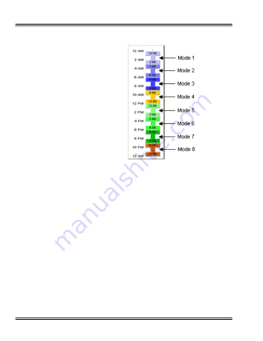
Figure 15  Standard View - Night Mode Switching Mode Colors

Summary of Contents for ELECTRA ELITE IPK II

Page 1: ...may occur causing slight variations When viewing and printing this document we cannot guarantee that your specific PC or printer will support all of the fonts or graphics Therefore when you view the d...

Page 2: ...PC PROGRAMMING MANUAL INT 1096 IPK II DOCUMENT REVISION 1...

Page 3: ......

Page 4: ...Inc Dterm is a registered trademark of NEC Corporation and Electra Elite is a registered trademark of NEC America Inc Windows is a registered trademark of Microsoft Corporation AT T is a registered tr...

Page 5: ......

Page 6: ...3 Application Layout 1 0 Menu 5 2 0 Toolbar 5 3 0 Submenu Area 5 4 0 Workspace 6 4 0 1 Title 6 4 0 2 Subtitle 6 4 0 3 Workspace Buttons 7 4 0 4 Navigation Area 7 4 0 5 Data Area 8 4 0 6 Help Area 8 5...

Page 7: ...ID Translation Table 18 8 0 Night Mode Switching 21 8 0 1 Adding a Time Frame 23 8 0 2 Removing a Time Frame 24 8 0 3 Moving a Time Frame 24 8 0 4 Modifying a Time Frame 25 8 0 5 Time Frame Duration 2...

Page 8: ...ue CAP Number to Each Key 47 3 0 Extension Numbers 48 4 0 Function Keys 50 10 Communications 1 0 Connect Disconnect 52 1 0 1 Accessing Connect 53 1 0 2 Using Connect 53 Connection Types 54 Login 54 1...

Page 9: ...Accessing Firmware Update 62 5 0 2 Using Firmware Update 62 Firmware Package File 62 Schedule 62 6 0 Feature Activation 63 6 0 1 Accessing Feature Activation 63 6 0 2 Using Feature Activation 63 Auto...

Page 10: ...10 Figure 7 Standard View Card Configuration 12 Figure 8 Standard View Class of Service for DISA E M Tie Lines 14 Figure 9 Standard View Class of Service for Telephones 16 Figure 10 Standard View Dep...

Page 11: ...ti Assignment CAP Keys Same 46 Figure 27 Multi Assignment CAP Keys Unique 47 Figure 28 Multi Assignment Extension Numbers 49 Figure 29 Multi Assignment Function Keys 50 Figure 30 Connect Disconnect St...

Page 12: ...wnload settings between PCPro and a KTS J Save settings to files that can be archived for later use J Program settings grouped by their relationship via Standard screens J Program settings sequentiall...

Page 13: ...entium III 598MHz minimum Pentium 4 2 5GHz recommended Memory 128 MB of RAM 256 MB recommended OS Microsoft Windows 2000 or higher Other Microsoft Internet Explorer 6 0 Communication port LAN RS232 or...

Page 14: ...folder being deleted Table 3 Default Folders Folder Location Description My Databases install dir databases Default folder where PCPro databases are saved My Log files install dir logfiles Default fol...

Page 15: ...via 3 different views Standard Wizard and System Data These methods can be accessed through the menu item Programming Accessing these items updates the applications Submenu and Workspace areas The Sta...

Page 16: ...a group of buttons that map to items in the application menu The toolbar allows for quick and convenient access to the most common PCPro commands The items on the toolbar are shown in Figure 2 PCPro T...

Page 17: ...bmenu Area and the Workspace itself Common Workspace components are further explained 4 0 1 Title Describes what the current settings in the Workspace are related to This is associated with the select...

Page 18: ...m data 3 Use the Previous button 4 Use the Next button 5 Save the active configuration 6 Exit the application 7 Generate a report 4 0 4 Navigation Area To navigate to different items with a PRG use th...

Page 19: ...iews available These are H Standard View H Wizards H System Data 4 0 6 Help Area The Help Area shows help text relevant for the data in the Data Area More extensive help can usually be found in the ap...

Page 20: ...ion Layout 9 5 0 STATUS BAR The status bar which is a horizontal area at the bottom of the Workspace provides information about the current state of what you are viewing in the Workspace and any other...

Page 21: ...d settings into one screen allowing a quick setup of a high level task Settings on these screens work together allowing users to understand how settings relate to each other Standard screens are ident...

Page 22: ...ing the purple cog icon The Standard View menu will then appear in the Programming submenu area Standard screens are ordered alphabetically To view a particular Standard View screen click on the scree...

Page 23: ...t To obtain card details download the configuration from the KSU The relevant card slots display the card type which they house the telephone trunk port range which the card uses and firmware version...

Page 24: ...rd Configuration screen as green cards These miscellaneous cards don t have a direct relationship to a trunk or telephone However some cards like Voice Mail under this category use telephone ports as...

Page 25: ...n to remove an existing card 3 Select the Delete Card item The card is removed and the slot and port type range it was utilizing is now available for use by another cards 4 0 CLASS OF SERVICE FOR DISA...

Page 26: ...nes are class members via this Night Mode selection Do this by completing the following 1 Select a Night Mode 2 Select which DISA Users and E M Tie Lines during this Night Mode are class members DISA...

Page 27: ...Class of Service Options Enable Disable telephone specific service options for the class These settings are linked with 20 07 20 08 20 09 20 10 20 11 20 12 and 20 13 Night Mode Assign when telephones...

Page 28: ...e Department Groups To setup up a Department Group complete the following 1 Specify a Department Group to modify 2 Specify basic characteristics of the Department Group 3 Select which extensions are P...

Page 29: ...ase priority by 1 J Shift Down Arrow Decrease priority by 1 J Shift Page Up Increase priority by one page J Shift Page Down Decrease priority by one page J Shift Home Make highest priority J Shift End...

Page 30: ...e Table Area during the selected Night Mode 5 Select which Trunk Groups will use the Table Area during the selected Night Mode 6 Specify Trunk Group specific DID settings Table Areas The DID Translati...

Page 31: ...use this to help define the Intercept Ring Group calls get forward to during Night Modes Do this by completing the following 1 Select a Night Mode 2 Select which Trunk Groups during this Night Mode w...

Page 32: ...ht Mode Service Group complete the following 1 Enable disable users from activating Night Mode Service via a service code 2 Enable disable Automatic Night Mode Service 3 Specify a Night Mode Service G...

Page 33: ...for the selected Night Mode Service Group Schedule Patterns can be made up of 20 times frames Each time frame is associated with a Night Mode These settings are linked with 12 03 See also 8 0 1 Addin...

Page 34: ...e starting time toward the end time A colored bar appears defining this time frame Keep the left mouse button down while dragging 2 Release the left mouse button A dialog then prompts for the Night Mo...

Page 35: ...ern bar Alternatively select the time frame and press the Delete key 8 0 3 Moving a Time Frame To move a time frame select it with the mouse and drag it to the desired position Surrounding time frames...

Page 36: ...to the desired change Surrounding time frames can limit changes because time frames cannot overlap To solve this problem either remove existing time frames or modify them 8 0 5 Time Frame Duration To...

Page 37: ...e call from the trunk to a voice mail type Individual settings can be applied to each Night Mode 2 Select a particular Incoming Ring Group 3 Select which extensions are members of the Incoming Ring Gr...

Page 38: ...des To setup up a Timer Class complete the following 1 Specify a Timer Class to modify 2 Set the various times for the class 3 Select a Night Mode 4 Select which trunks are members of the Time Class d...

Page 39: ...ass during the selected Night Mode These settings are linked with 20 30 Extensions Lists which extensions are members of the class during the selected Night Mode These settings are linked with 20 29 1...

Page 40: ...h 14 07 The various access types are listed below Night Mode Assign which extensions use the Trunk Access Map for this Night Mode selection Do this by completing the following 1 Select a Night Mode 2...

Page 41: ...n be used by trunks and extensions To setup a Trunk group complete the following 1 Specify a Trunk Group entry to modify 2 Select which trunks are members of the Trunk Group 3 Prioritize trunks by ord...

Page 42: ...e priority of trunks within the Trunk Group These settings are linked with 14 05 02 When a trunk is selected as part of the Trunk Group it will automatically appear in the priority list the list to th...

Page 43: ...ons use the Route Table Entry during the selected Night Mode This list applies to extensions using the Trunk Service Code to access trunks These settings are linked with 21 02 Extensions using Alterna...

Page 44: ...System Data guiding users in the successful setup of a KTS feature Wizards are identified by their name This name indicates the feature to which the Wizard is related A Wizards System Data is grouped...

Page 45: ...owing J Select the menu item Programming Wizards or J Select the toolbar icon depicting the wand or J Press the F10 key or J If the Programming submenu area is currently open select the tab below depi...

Page 46: ...te steps 2 and 3 till all screens are finished 5 Apply changes When programming a Wizard changes to system data are applied J whenever the Apply button is pressed J whenever the user moves to a differ...

Page 47: ...G identifier can be seen below 10 02 is the ID and Location Setup is the name 10 02 Location Setup PRGs are grouped by their relationship into PRG Groups PRG Groups are identified by their ID and name...

Page 48: ...Electra Elite IPK II Document Revision 1 System Data 37 Figure 22 System Data Submenu...

Page 49: ...oolbar icon depicting the blue block or J Press the F11 key or J If the Programming submenu area is currently open select the tab below depicting the blue block icon The System Data View Menu will the...

Page 50: ...on the screen 3 Apply changes When programming system data changes are applied J Whenever the Apply button is pressed J Whenever the user changes the system data item link J Whenever the user modifies...

Page 51: ...ave As The modification history is a running list of the changes PCPro keeps appending to the list So if a user opens a file makes some changes saves and closes the file In the future opens the same f...

Page 52: ...odification icon on the Status Bar The different states are The database is not modified All data has been saved to file and uploaded System data has been modified and has not been saved to file Syste...

Page 53: ...e g one trunk to another This copy only applies to single PRG Copy only appears on screens where it is applicable To copy an item complete the following 1 Press the Copy button 2 Specify the source t...

Page 54: ...from Only a single source item can be selected Destination The destination details the item being copied to Multiple destination items can be selected Elements Specify what settings should be copied f...

Page 55: ...e time over having to enter each account code individually The dialog is found under the menu item Programming Multi Assignment Account Codes To assign a range of account code BINs with numbers follow...

Page 56: ...l be BIN 001 00001 BIN 002 00003 BIN 003 00005 BIN 010 00019 2 0 CALL APPEARANCE KEYS The Call Appearance Keys multi assignment dialog enables the user to setup a group of function keys as CAP keys fo...

Page 57: ...the system and assign them to the selected function keys The values have not been set to system data yet This is only a preview 5 If required edit the actual value for each function key 6 Click the A...

Page 58: ...elephones follow the steps below 1 Select the telephones from the Telephones list by ticking the check boxes 2 Select which function keys to set buy ticking the checkbox 3 Select the Unique CAP number...

Page 59: ...atively click the button and select CAP 0010 from the selection box 5 Click the Apply button to trigger the assignment The result will be 3 0 EXTENSION NUMBERS The Extension Number multi assignment di...

Page 60: ...tton to trigger the assignment Example To assign telephone ports 001 099 with extension numbers 301 399 1 Since we want to assign station numbers we select 11 01 Extension Numbering as our extension t...

Page 61: ...f the need is to setup many telephones to have the same set of function keys The dialog is found under the menu item Programming Multi Assignment Function Keys 1 Select the telephones from the Telepho...

Page 62: ...eys 1 to 8 i e tick all items in the first row of function keys 3 Set the function type to Trunk Key 4 In the Start with Trunk edit box type 10 Alternatively click the button and select trunk 10 from...

Page 63: ...NECT Makes breaks a connection session between PCPro and a KTS This option changes its functionality depending on the connection status of PCPro The connection status is indicated on the tool bar Whil...

Page 64: ...Pro is disconnected from a KTS access the Connect dialog via either of the following H Select the menu item Communications Connect Disconnect or H Select the icon depicting the disconnected black and...

Page 65: ...to the PC Specify the modem to use and the number to dial H IP An IP Connection can be made via a LAN or the Internet The IP address specified must match the KTS setting 10 12 01 Login Specify the Use...

Page 66: ...munications methods excluding Connect Disconnect are then disabled and the Connect Disconnect toolbar icon changes status to disconnected 2 0 DOWNLOAD A download will pull all the data off the KTS and...

Page 67: ...the Close button Transfer Type Select a filter that controls the scope of KTS settings to download The following Transfer Types are made available H All No filter all KTS settings H Card Configuratio...

Page 68: ...n status The filter only applies to system data on the PCPro side not system data residing in KTS memory Refer to 7 Modification History on page 1 40 for further information 3 0 UPLOAD A upload will p...

Page 69: ...he Close button Transfer Type Select a filter that controls the scope of KTS settings to upload The following Transfer Types are made available H All No filter all KTS settings H Card Configuration Ca...

Page 70: ...r to 7 Modification History on page 1 40 for further information 4 0 SYSTEM INITIALIZATION A System Initialization resets a KTS During an initialization all telephone calls are dropped and all connect...

Page 71: ...n Dialog there are two types of initialization 1st Initialization A 1st Initialization resets the KTS and loads all system data with factory default values As a result all previously modified values a...

Page 72: ...effort in comparison to performing the task manually A Firmware Update can only occur when PCPro is connected to a KTS The time to upload the firmware package file is directly related to the file size...

Page 73: ...s the Firmware Update dialog by selecting the menu item Communications Firmware Update 5 0 2 Using Firmware Update Within the Firmware Update Dialog perform a Firmware Update by completing the followi...

Page 74: ...ion When PCPro is connected to a KTS access the Feature Activation dialog by selecting the menu item Communications Feature Activation 6 0 2 Using Feature Activation Within the Feature Activation Dial...

Page 75: ...s the Activate button PCPro will then begin the activation process This process consists of PCPro will attempt to contact the NEC Product Activation server on the internet The information entered is v...

Page 76: ...to activate 4 Specify the Activation Code for the features you wish to activate 5 Press the Activate button Associate Number An Associate Number identifies the dealer requesting the Feature Activation...

Page 77: ...odes are provided by the Activation Server Activating at a Later Time PCPro provides the ability to save the feature activation information to the PCPro database file Clicking the Activate Later butto...

Page 78: ...he DbgTerm icon on the toolbar If PCPro is connected via LAN to a KTS then the debug terminal will automatically try and connect to the same IP address domain name Once the debug terminal is running i...

Page 79: ...f loading user defined connection settings They are application wide settings Connection Accounts can be created in two ways 1 Via the Connect dialog 2 Via the Connection Accounts dialog 1 0 CREATING...

Page 80: ...ext describing the connection 6 Press the OK button 2 0 CREATING FROM THE CONNECTION ACCOUNTS DIALOG To create a Connection Account via the Connection Accounts dialog select the menu item Tools Connec...

Page 81: ...lbar Reference 13 Menu Toolbar Reference Menu Item Submenu Level 1 Item Submenu Level 1 Item Toolbar Icon Shortcut Key Sequence File New Ctrl N Open Ctrl O Save Ctrl S Save As Send Properties Log off...

Page 82: ...e Settings Multi Assign Account Codes Call Appearance Extension Numbers Function Keys Communications Connect Disconnect F5 Download F6 Ctrl D Upload F7 Ctrl U System Initialization Firmware Update Mai...

Page 83: ...rvice Maintenance Modification History Numbering Plan System Configuration System Data Verify F8 Debug Terminal Import IPK Converted File Speed Dials Export Speed Dials PCPro Accounts Connection Accou...

Page 84: ......

Page 85: ...PC PROGRAMMING MANUAL NEC Unified Solutions Inc Document Revision 1...

Reviews: