D
term
Cordless Lite
®
All manuals and user guides at all-guides.com
all-guides.com
Page 1: ...Dterm Cordless Lite All manuals and user guides at all guides com a l l g u i d e s c o m ...
Page 2: ...y its employees and customers The information contained herein is the property of NEC America Inc and shall not be reproduced without prior written approval from NEC America Inc Dterm is a registered trademark of NEC America Inc Copyright 1998 NEC America Inc 1555 Walnut Hill Lane Irving TX 75038 Business Terminals Division All manuals and user guides at all guides com ...
Page 3: ...3 Important Safety Instructions 1 3 Section 4 Important Electrical Considerations 1 6 Range 1 6 Telephone Line Problems 1 6 Radio Interference 1 7 More than One Cordless Telephone 1 7 Chapter 2 About the Dterm Cordless Section 1 Items Included with the Dterm Cordless Lite 2 1 Section 2 Optional Accessories and Replacement Parts 2 2 Section 3 Features of the Cordless Telephone 2 2 All manuals and u...
Page 4: ...ng Unit 3 3 Section 4 Wall Installation 3 5 Standard Wall Plate Mounting 3 5 Direct Wall Mounting 3 7 Charging Unit Wall Mounting 3 9 Section 5 Attaching the Belt Clip to the Handset 3 11 Section 6 Installing the Handset Battery Pack 3 12 Section 7 Charging Batteries 3 14 Charging the Handset Battery Pack 3 14 Charging Spare Battery Packs 3 15 Low Battery Indicator 3 16 Cleaning the Battery Charge...
Page 5: ...ine Terminal 4 7 Completing a Call using the NEC Digital Multiline Terminal 4 8 Section 5 Making a Call Using the Dterm Cordless Lite 4 8 Making a Normal Call 4 8 Section 6 Dedicated Feature Operations 4 9 Placing a Call on Hold 4 10 Muting a Call 4 10 Transferring Calls 4 10 Setting up a Conference Call 4 11 Locking and Unlocking the Keypad 4 11 Chapter 5 Optional Equipment Installation Section 1...
Page 6: ...erm Cordless Lite to the Multiline Terminal 3 2 Figure 3 3 Applying Power to the Charging Cradle 3 3 Figure 3 4 Polarized Plug 3 4 Figure 3 5 Attaching the Wall Mount Stand to the Base Unit 3 5 Figure 3 6 Placing the AC Adapter Cord Inside the Wall Mount Stand 3 5 Figure 3 7 Placing the Base Unit on the Posts of the Wall Plate 3 6 Figure 3 8 Plugging the AC Adapter into the AC Wall Outlet 3 6 Figu...
Page 7: ...to Expose the Belt Clip Notch 3 11 Figure 3 16 Attaching the Belt Clip to the Handset 3 11 Figure 3 17 Removing the Belt Clip 3 12 Figure 3 18 Removing the Battery Cover 3 12 Figure 3 19 Replacing the Battery Pack 3 13 Figure 3 20 Replacing the Battery Cover 3 13 Figure 3 21 Charging Unit 3 14 Figure 3 22 Charging the Battery Pack 3 15 Figure 3 23 Battery Low Indicator 3 16 Figure 3 2 Cleaning Bat...
Page 8: ...Inc Issue 1 Dterm Cordless Lite Owner s Manual vii Figure 4 5 Cordless and Desk Buttons 4 7 Figure 4 6 Special Operations Keys 4 9 Figure 5 1 Installing the Headset 5 1 All manuals and user guides at all guides com ...
Page 9: ...Dterm Cordless Lite Owner s Manual ix List of Tables Table 3 1 Low Battery 3 16 Table 4 1 Handset Control Functions 4 1 Table 6 1 Troubleshooting 6 1 All manuals and user guides at all guides com ...
Page 10: ...quency Control Phase Lock Loop Modulation MFK Operating Temperature 10 50 C Receive Transmit Frequency 902 MHz 928 MHz Power Requirements 10V DC from supplied AC adapter Size 4 1 4 in W x 7 1 2 in D x 2 1 4 in H Weight Approximately 15 4 oz Receive Transmit Frequency 902 MHz 928 MHz Power Requirements Rechargeable sealed lead acid battery pack All manuals and user guides at all guides com ...
Page 11: ...er can damage the battery or cause the battery to explode Size 2 1 4 in W x 1 1 2 in D x 8 1 2 in H with antenna Weight Approximately 8 8 oz with battery Battery Capacity 500 mAh 4 0V Talk Mode 5 hours typical Standby Mode 40 hours typical Specifications shown are typical and subject to change without notice Power Requirements 9V DC from supplied AC adapter Size 3 1 2 in W x 4 3 4 in D x 3 1 4 in ...
Page 12: ... 5 Do not place this product on an unstable cart stand or table The telephone can fall causing serious damage to the unit 6 To protect the product from overheating do not block or cover any slots or openings in the base unit This product should never be placed near or over a radiator or heat register This product should not be placed in a built in installation unless the proper ventilation is prov...
Page 13: ... Unplug this product from the wall outlet and refer servicing to qualified service personnel under the following conditions When the power supply cord is damaged or frayed If liquid has been spilled onto the product If the product has been exposed to water or rain If the product does not operate normally when following the operating instructions Adjust only those controls that are covered by the o...
Page 14: ...ttery or conductor can overheat and cause burns 5 Charge the battery pack provided with or identified for use with this product only in accordance with the instructions and limitations specified in the instruction manual provided for this product 6 Observe proper polarity orientation between the battery pack and battery charger Privacy Cordless telephones are radio devices Communications between t...
Page 15: ...eiving according to the highest specifications set forth by the FCC We have rated this phone to operate at a maximum distance with the qualification that the range depends upon the environment in which the telephone is used Many factors limit range and it would be impossible to include all of the variables in our rating The maximum range rating of this telephone is meant to be used as a means of c...
Page 16: ...performance ensure that the antenna on the base unit is fully extended In the unlikely event that you consistently hear other voices or distracting transmissions on your telephone you may be receiving radio signals for another cordless telephone or other source of interference If you cannot eliminate this type of interference you need to change to a different channel Finally it should be noted tha...
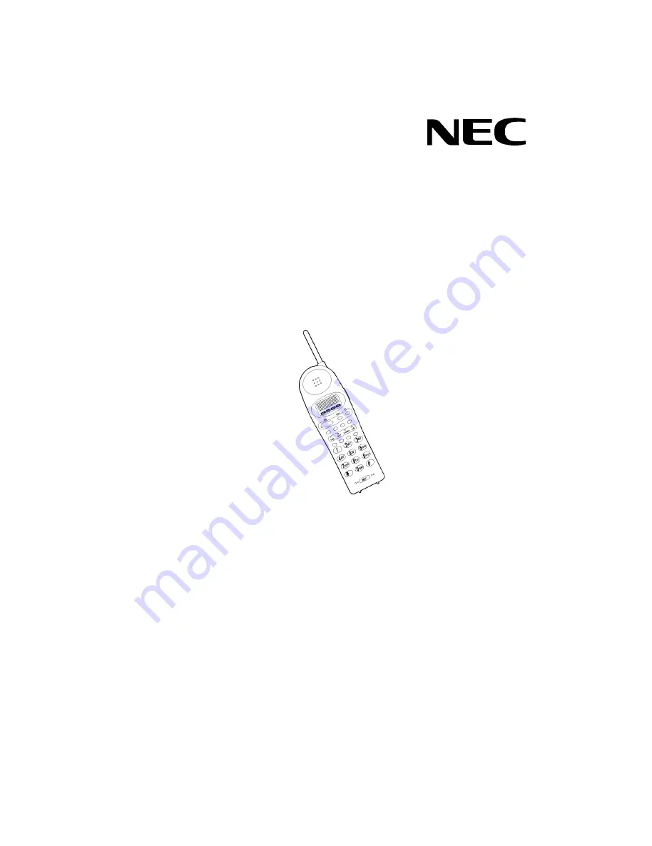
Page 17: ...andards for reliability long life and outstanding performance To become familiar with the features of the cordless telephone read this manual thoroughly The Dterm Cordless Lite includes the following items Figure 2 1 Items Included with the Dterm Cordless Lite Base Unit Handset Telephone Cord 2 AC Adapters 2 Rechargeable Batteries Spring type Belt Clip Battery Charger Wall Plate Adapter All manual...
Page 18: ... THE CORDLESS TELEPHONE The Dterm Cordless Lite telephone provides a variety of features These features are listed below 900 MHz Digital 2 line 16 digit LCD Display Figure 2 2 Optional Accessories and Replacement Parts Telephone Cord AC Adapter 400 mAh Battery BT 9000 Spring type Belt Clip Headset Base Unit Wall Mount Charger and AC Adapter EXP9685 Leather Case EXP9683 All manuals and user guides ...
Page 19: ... Spare Battery AutoStandby AutoTalk Silent Alarm Out of Range Protection Low Battery Protection System Key Pad Lock Feature Wall Mountable Separate Base Unit Wall Mountable Separate Charging Unit Easy Installation Compact Handset Design Use with an NEC Digital Multiline Terminal or as a stand alone device The Dterm Cordless Lite can be used in conjunction with the Electra Professional Electra Elit...
Page 20: ...tions of the cordless telephone handset Figure 2 3 Handset Controls and Functions 1 Ringer ON OFF Switch 8 Microphone 2 LCD Icons 9 Handset Jack 3 Talk Key talk 10 Channel Key chan 4 Function Keys F1 F4 11 Volume Key vol 5 Hold Key hold 12 Mute Key mute 6 Conference Key conf 13 Transfer Key transfer 7 Dial Pad All manuals and user guides at all guides com ...
Page 21: ...ess Lite Owner s Manual 2 5 SECTION 5 BASE UNIT CONTROLS Figure 2 4 Base Unit Controls identifies the controls of the telephone base unit Figure 2 4 Base Unit Controls All manuals and user guides at all guides com a l l g u i d e s c o m ...
Page 22: ...r Keep the base unit and handset away from sources of electrical noise motors fluorescent lighting computers PC monitor Refer to Chapter 1 Specifications and Safety Information for a complete discussion of safety precautions SECTION 2 CONNECTING THE TELEPHONE CORDS When connecting the telephone cords observe the following precautions Never install telephone wiring during a lightning storm Never to...
Page 23: ...2 Connect a qualified NEC digital Multiline Terminal to the Dterm Cordless Lite Figure 3 1 Connecting Telephone Cords to the Telephone Jack Figure 3 2 Connecting the Dterm Cordless Lite to the Multiline Terminal To digital Multiline Terminal interface card on KTS PBX Line OUT To Multiline Terminal All manuals and user guides at all guides com ...
Page 24: ...rged either in or out of the handset The AC adapter furnished with this telephone may be equipped with a polarized line plug a plug having one blade wider than the other This plug will fit into the power outlet only one way If you are unable to insert the plug fully into the outlet try reversing the plug Refer to Figure 3 4 Polarized Plug If you cannot plug the AC adapter into the outlet the outle...
Page 25: ... Route the power cord where it will not create a trip hazard or where it could become chafed and create a fire or other electrical hazards Figure 3 4 Polarized Plug Do not alter the shape of the blades of the polarized plug All manuals and user guides at all guides com ...
Page 26: ...1 Slide the wall mount stand into the notches at the top of the base unit Rotate the wall mount stand down and snap it into place 2 Plug the AC adapter into the base unit 3 Place the AC adapter cord inside the molded channel of the wall mount stand Figure 3 5 Attaching the Wall Mount Stand to the Base Unit Figure 3 6 Placing the AC Adapter Cord Inside the Wall Mount Stand All manuals and user guid...
Page 27: ...wall mount stand 5 Plug the other end of the short telephone cord into the modular wall jack in the center of the wall plate 6 Place the base unit on the posts of the wall plate and push down until it is firmly seated 7 Plug the AC adapter into a standard 120 Vac wall outlet Note Do not use an outlet controlled by a wall switch Figure 3 7 Placing the Base Unit on the Posts of the Wall Plate Figure...
Page 28: ... could cause a hazard when inserting screws into the wall Make sure the wall material is capable of supporting the weight of the base unit Use 10 screws with anchoring devices suitable for the wall material where the base unit will be placed To mount the telephone 1 Insert two mounting screws 3 15 16 inches apart Allow about 3 16 of a inch between the wall and screw heads for mounting the telephon...
Page 29: ... Electra Professional or Electra Elite Multiline Terminal into the PHONE jack Place the telephone cords inside the molded channels on the bottom of the wall mount stand 5 Place the base unit on the posts of the wall screws and push down until it is firmly seated Figure 3 10 Placing the Telephone Cords into Inside the Wall Mount Stand Figure 3 11 Attaching the Wall Mount Unit to the Wall All manual...
Page 30: ...ounting the charging unit consider the following Select a location away from electrical cables pipes or other items behind the mounting location that could cause a hazard when inserting screws into the wall Make sure the wall material is capable of supporting the weight of the charging unit Use 10 screws with anchoring devices suitable for the wall material where the charging unit will be placed 1...
Page 31: ...apter cord around the strain relief 3 Place the charging unit on the posts of the wall screws and push down until it is firmly seated Figure 3 13 Wrapping the AC Adapter Cord around the Strain Relief Figure 3 14 Placing the Charging Unit on the Wall All manuals and user guides at all guides com a l l g u i d e s c o m ...
Page 32: ...lip can be used to attach the handset to a belt or pocket for convenient portability 1 Snap the tab out of the belt clip notch on the top of the handset 2 Slide the clip into the tab slot Press firmly until it snaps into place The belt clip is designed to fit snugly onto the handset Figure 3 15 Removing the Tab to Expose the Belt Clip Notch Figure 3 16 Attaching the Belt Clip to the Handset All ma...
Page 33: ...ip up at the same time Once the belt clip is removed remember to reinstall the cover tab SECTION 6 INSTALLING THE HANDSET BATTERY PACK 1 Remove the battery cover by pressing the latch an sliding the cover down and off of the handset Figure 3 17 Removing the Belt Clip Figure 3 18 Removing the Battery Cover All manuals and user guides at all guides com ...
Page 34: ... pack down into the handset Note It may be necessary to remove the old battery at this time 3 Place the cover and slide it up until it latches onto the handset Figure 3 19 Replacing the Battery Pack Figure 3 20 Replacing the Battery Cover All manuals and user guides at all guides com ...
Page 35: ...nterruption for five to eight hours 1 Place the handset in the front slot of the charging unit 2 Make sure the CHARGE 1 indicator lights If the CHARGE 1 LED does not come on check to see if the AC adapter is plugged in and that the handset is making good contact with the charging contacts on the charging unit Note The CHARGE 1 LED turns red during and after charging the handset with the battery Fi...
Page 36: ...t light check that the AC adapter is plugged in and that the battery pack is making contact with the charging contracts on the charging unit Charging is complete when the CHARGE 2 LED goes off Note Charge the battery pack without interruption for five to eight hours 3 When charging is complete press out on the latch and remove the battery pack for use If the battery pack is not needed immediately ...
Page 37: ... to be taken during a call or in standby mode when low battery indication is displayed Figure 3 23 Battery Low Indicator Table 3 1 Low Battery On a Call In Standby Mode What occurs when batt low is displayed Only the talk key operates None of the keys operate Handset beeps once every three seconds Handset beeps every 15 seconds for 15 minutes Action Complete the call as quickly as possible Cannot ...
Page 38: ...o clean all charging contacts on the handset and charging unit about once a month Use a pencil eraser or other contact cleaner Do not use liquids or solvents SECTION 8 ANTENNA Before using the Dterm Cordless Lite raise the antenna to the vertical position Figure 3 2 Cleaning Battery Charge Contacts All manuals and user guides at all guides com ...
Page 39: ...and vol volume keys are used to control various functions Table 4 1 Handset Control Functions explains the handset controls Figure 4 1 Handset Controls Table 4 1 Handset Control Functions Condition Action LCD Display Talk Key Standby Mode Press talk on the front of the handset to make a call The telephone first acquires a line to the base All manuals and user guides at all guides com ...
Page 40: ... or low receive volume level This function provides volume control to the handset or to an accessory headset No display indications Ringer Select Standby Mode Press vol on the front of the handset to select one of the following settings Ring Type A High Ring Type A Low Ring Type B High Ring Type B Low Ring Off Silent Alarm Table 4 1 Handset Control Functions Condition Action LCD Display All manual...
Page 41: ... in the LCD When communication is made between the base unit and the handset the LCD is blank and the telephone is ready to use Figure 4 2 Acquiring Link Condition Indicator LCD Display Line OK TALK Icon No Connection to Base Unit Error Tone NO SERVICE Channel Busy Error Tone SYSTEM BUSY Line in Use Error Tone LINE IN USE No Line Selected TALK Icon NO LINE SELECTED Figure 4 3 Standby Mode All manu...
Page 42: ...call is received the handset rings and the LED on one of the function keys assigned to a line key flashes 2 Pick up the handset The AutoTalk feature allows the call the be answered immediately Figure 4 4 No Service During a Call In Standby Mode Condition Warning Tone Cannot make or answer calls telephone may ring intermittently Action Move back in range within 20 seconds Check power to the base un...
Page 43: ... 2 Press the function key with the flashing LED to answer the call OR Press talk to answer the incoming call Note 1 The Ringing Line Preference feature must be enabled in order to answer calls with the talk key Contact the authorized NEC Dealer to for programming this feature Note 2 If two or more calls come in at the same time pressing the talk key answers the prime line 3 When the call is finish...
Page 44: ... the vol key to advance to the next function key F2 F4 6 After programming F4 press the vol key to advance to Global Off Hook Ringing Assignment 7 Press chan to turn Global Off Hook Ringing ON OFF LCD indicates ON or OFF as appropriate 8 Press the talk key to exit Note 1 Function keys F1 F4 can be programmed as Line Keys 1 16 Redial LNR SPD Answer ANS Feature FNC or Recall When assigned these keys...
Page 45: ...ine Terminal Switching held calls between the Dterm Cordless Lite and the associated Multiline Terminal is not recommended since line key LED indications will not be provided Use the base unit on the Dterm Cordless Lite to switch between the Dterm Cordless Lite and the Multiline Terminal Press Cordless to select the Dterm Cordless Lite OR Press Desk to select the Multiline Terminal Refer to Figure...
Page 46: ...skset is programmed Refer to Section 6 Dedicated Feature Operations This section describes normal call handling Making a Normal Call 1 Remove the handset from the charging unit 2 Press the talk key The talk icon appears after the handset and base unit are connected OR Press the designated function key programmed as a line key When dial tone is heard enter the number to be called The display shows ...
Page 47: ... unit press talk to hang up the telephone SECTION 6 DEDICATED FEATURE OPERATIONS Calls can be placed on hold transferred to another extension or two or more parties can be conferenced These operations depend upon how they are set up in the key system Caution The handset must be within range of the base for the special operations to function properly Figure 4 6 Special Operations Keys All manuals a...
Page 48: ... Press the mute key on the handset during a call The talk icon blinks on the display 2 To turn mute off press the mute key again and the call is restored Transferring Calls Calls can be forwarded to another extension To transfer a call 1 Press the transfer key and the phone number of the transfer destination 2 Wait for the party to answer then press the talk key to hang up The two parties can now ...
Page 49: ...second number for the second party 4 Press the conf key again A 3 party conference is now established If any party hangs up the conference only includes the remaining parties Locking and Unlocking the Keypad The Dterm Cordless Lite can be locked so no outgoing calls can be made Locking the Keypad To lock the telephone 1 Press and hold the chan key for one second while in standby mode A code input ...
Page 50: ...gain to confirm the entry The display is blank and the lock icon is displayed Unlocking the Keypad 1 Press and hold the chan key for one second while in standby mode A code input and the lock icon appear in the display 2 Enter the 2 digit number used to lock the telephone The code appears in the display All manuals and user guides at all guides com ...
Page 51: ...red correctly a beep is heard and the LCD clears The telephone goes into standby mode OR If the 2 digit number is entered incorrectly an error tone is heard when chan is pressed The LCD clears but the lock icon remains on as the telephone goes into standby mode All manuals and user guides at all guides com a l l g u i d e s c o m ...
Page 52: ...HEADSET EXP9530 The optional headset provides a handsfree option for the Dterm Cordless Lite With the headset installed the user can use the belt clip the carry the handset and conduct a conversation using the headset To install the headset Open the cover over the headset jack and plug the headset into the receptacle Figure 5 1 Installing the Headset All manuals and user guides at all guides com ...
Page 53: ...ttings are needed Operation of the headset is the same as the handset However the user hears through the headset earphone and talks through the headset microphone The handset earphone and microphone mouthpiece are disconnected All manuals and user guides at all guides com ...
Page 54: ... sure the handset is properly seated in the charging unit Make sure the lead acid battery pack is properly placed on the handset Make sure that the charging contacts on the handset and charging unit are clean Charge 2 light will not come on when the spare battery is placed in the charging unit low battery only Make sure the AC adapter is plugged into the charging unit and wall outlet Make sure the...
Page 55: ...the base unit Handset does not ring The lead acid battery may be weak Charge the battery pack for eight hours Make sure the base unit antenna is fully vertical The handset may be too far from the base unit Table 6 1 Troubleshooting Problem Suggestion All manuals and user guides at all guides com ...
Page 56: ...Dterm Cordless Lite All manuals and user guides at all guides com a l l g u i d e s c o m ...