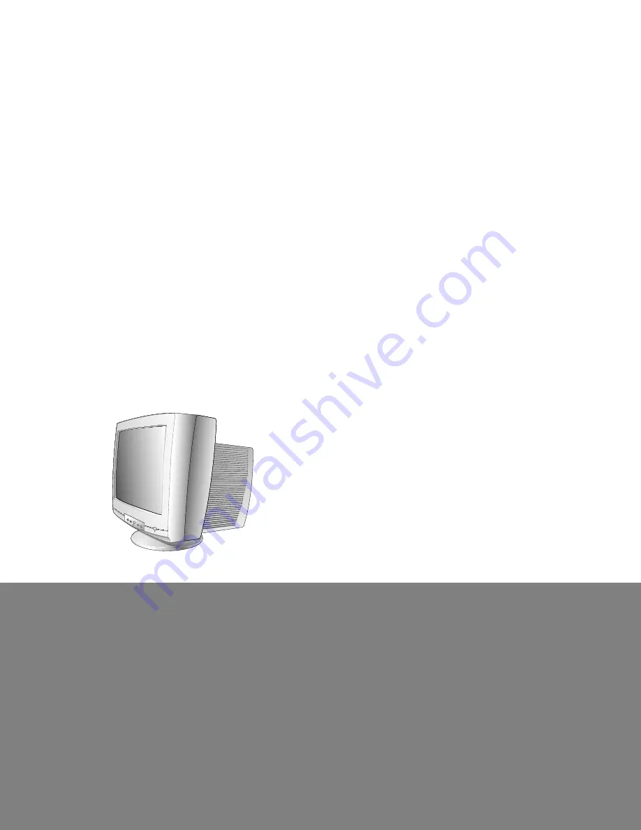
COLOR MONITORSERVICE MANUAL
CAUTION
BEFORE SERVICING THE UNIT, READ THE SAFETY PRECAUTIONS IN THIS MANUAL.
CHASSIS NO. : CA-134FACTORY MODEL: AS120J
MODEL: AS120-1, AS120-BK-1
Page 1: ...COLOR MONITOR SERVICE MANUAL CAUTION BEFORE SERVICING THE UNIT READ THE SAFETY PRECAUTIONS IN THIS MANUAL CHASSIS NO CA 134 FACTORY MODEL AS120J MODEL AS120 1 AS120 BK 1 ...
Page 2: ...mage Size 366 0 x 274 5mm 14 40 x 10 80 Preset Image Size 350 x 262 mm 13 78 x 10 31 4 2 Display Color Full Colors 4 3 Display Resolution 1600 Dots x 1200Lines 75Hz 4 4 Video Bandwidth 203MHz 5 ENVIRONMENT 5 1 Operating Temperature 0 C 40 C 32 F 103 F Ambient 5 2 Relative Humidity 10 90 Non condensing 5 3 Altitude 10 000 ft 6 DIMENSIONS with TILT SWIVEL Width 498 mm 19 60 Depth 512 mm 20 18 Height...
Page 3: ...ed per the original design Soldering must be inspected for the cold solder joints frayed leads damaged insulation solder splashes or the sharp points Be sure to remove all foreign materials IMPLOSION PROTECTION All used display tubes are equipped with an integral implosion protection system but care should be taken to avoid damage and scratching during installation Use only same type display tubes...
Page 4: ...0 0 318 0 064 1 049 640 x 480 60Hz Yes MODE 3 43 269 23 111 17 778 5 334 1 556 1 556 2 222 85 008 11 763 11 093 0 670 0 023 0 069 0 578 640 x 480 85Hz Yes MODE 4 60 023 16 660 13 003 3 657 0 203 1 219 2 235 75 029 13 328 12 795 0 533 0 017 0 050 0 466 1024 x 768 75Hz Yes MODE 5 68 677 14 561 10 836 3 725 0 508 1 016 2 201 84 997 11 765 11 183 0 582 0 015 0 044 0 523 1024 x 768 85Hz Yes MODE 6 79 9...
Page 5: ...WIRING DIAGRAM 6 P301 P302 P303 Signal Cable AC Socket FBT P801 S S P901 P701 P452 P453 P451 P401 P503 P402 ...
Page 6: ...BLOCK DIAGRAM 7 SIGNAL INPUT ...
Page 7: ...omes stand by and suspend mode It s power consumption is below 8W When no horizontal and vertical sync signal input it s power consumption is below 3W 5 X ray Protection This circuit detects the rectified DC voltage comes from the FBT pin 4 If the high voltage of the FBT reaches up to about 30kV abnormal state H V control IC802 detects It stops B voltage supplied to the FBT T701 and high voltage i...
Page 8: ...7 Image Rotation Tilt Circuit This circuit corrects the tilt of the screen by supplying the image rotation signal to the tilt coil which is attached to the CDT near the deflection 18 Static Convergence Control Circuit This circuit corrects the convergence of the screen by supplying the convergence signal to the H V STC coil which is attached to the CDT near the deflection 19 Moire Reduction Circui...
Page 9: ...on the IBM compatible PC 3 EEPROM ALL CLEAR Y Yes command Caution Do not run this procedure unless the EEPROM is changed All data in EEPROM mode data and color data will be erased 4 COMMAND PRESET START Y Yes command 5 DIST ADJ FOS ADJ command 6 Adjust H POSITION as arrow keys to center of the screen 7 Adjust H SIZE as arrow keys to 390 2mm 8 Adjust V POSITION as arrow keys to center of the screen...
Page 10: ...8 0 003 on the White Balance Meter with PC arrow keys 15 Adjust SUB CONTRAST command to 36 1FL of the raster luminance 15 Display color 15 0 full white patten at Mode 7 16 COLOR ADJ LUMINANCE ABL command 17 Adjust ABL to 26 1FL of the luminance 18 Exit from the program 6 Adjustment for Focus 1 Display H character in full screen at Mode 7 2 Adjust two Focus control on the FBT that focus should be t...
Page 11: ... TROUBLE IN FUSE F901 TROUBLE IN IC901 CHECK FUSE OK F901 CHECK D901 BRIDGE DIODE NO YES YES NO NO CHECK C905 VOLTAGE 145VDC at 110V input 310VDC at 220V input TROUBLE IN D924 D926 D923 D922 D921 D920 TROUBLE IN Q912 Q913 Q915 Q914 IC903 IC904 Q902 YES NO CHECK D924 D926 D923 D922 D921 D920 YES ...
Page 12: ...2 PIN 19 20 21 PIN 10 5V CHECK IC303 PIN 1 3 5 PIN10 12V PIN 6 80V TROUBLE IN P301 SIGNAL CABLE PC SIGNAL TROUBLE IN IC302 P302 TROUBLE IN IC303 TROUBLE IN CDT SOCKET NO YES NO NO YES YES CHECK R G B CATHODE VOLTAGE TROUBLE IN IC304 NO YES NO CHARACTER ...
Page 13: ...T D924 D926 CATHODE 190V D923 D929 CATHODE 80V IC904 OUT 12V D921 CATHODE 6 3V CHECK IC401 MICOM PIN 6 5V HIGH IC801 PIN 10 12V HIGH ROTATE SCREEN CONTROL KNOB TO CLOCKWISE or COUNTER CLOCKWIES TROUBLE IN IC401 MICOM IC801 TROUBLE IN CDT SOCKET BOARD TROUBLE IN PRIMARY CIRCUIT OF T901 TROUBLE IN P302 SIGNAL CABLE AMBER GREEN OK YES NO YES NO ...
Page 14: ...N NO V DEFLECTION ONE HORIZONTAL LINE CHECK IC601 Pin 3 15V CHECK IC601 PIN 7 47V TROUBLE IN T901 15V LINE TROUBLE IN T701 47V LINE TROUBLE IN IC601 V CIRCUIT NO NO YES YES CHECK IC801 PIN 12 SAWTOOTH WAVE TROUBLE IN IC801 NO YES ...
Page 15: ...DE TROUBLE IN X401 IC401 TROUBLE IN IC401 TROUBLE IN IC401 TROUBLE IN T901 or PC INPUT H V SYNC SIGNAL NO H V SYNC SIGNAL NO NO NO DPMS TABLE Mode Item NORMAL STAND BY SUSPEND OFF H V SYNC ON ON OFF ON ON OFF OFF OFF LED GREEN AMBER AMBER AMBER VIDEO NORMAL OFF 0V OFF 0V OFF 0V YES YES CHECK B LINE 12V 15V 80V 5V TROUBLE IN Q913 Q915 NO YES STAND BY SUSPEND DPMS OFF MODE FAILURE ...
Page 16: ...HECK IC401 PIN 6 5V CHECK Q920 COLLECTOR VOLTAGE 0 5V CHECK P901 CHECK RL901 TROUBLE IN IC401 MICOM TROUBLE IN D925 TROUBLE IN P901 TROUBLE IN RL901 TROUBLE IN TH901 DEGAUSSING COIL NO DEGAUSSING NO NO NO NO YES YES YES YES ...
Page 17: ...off mode it color changes to orange 3 Adjust Buttons Use these buttons for adjusting the level of the selected item 4 SELECT Button Use these button for selecting an OSD icon to be adjusted 5 OSD Select Buttons Use these buttons to choose items in the on screen display REAR VIEW FRONT VIEW Front Control Panel Front Control Panel Power ON OFF Button Power Indicator D Sub Signal Connector AC Power S...
Page 18: ... 18 EXPLODED VIEW A 1 3 4 10 11 12 13 14 14 14 14 14 15 14 16 17 5 5 5 2 6 7 5 8 B 9 ...
Page 19: ...te BACK COVER ASSEMBLY CN291E D001E E CORE AS120 Black TILT SWIVEL ASSY CN291B NEC B002 T002 8A793 White TILT SWIVEL ASSEMBLY AS120J TKB002A TKT002A AF 320T STEALTH BLACK SCREW ASSEMBLY TAPTITE P TYPE D5 0 L25 0 MSWR FZMY METAL ASSY FRAME CN291E NEC COIL DEGAUSSING LX31 GET 1410MM 0 55 120TS 12 5 OHM W O PURITY FBT FLY BACK TRANSFORMER FQM19A015 UL TUBE AS120J SAMSUNG 19 FILTER CIRC EMC 02MD5 DELT...
Page 20: ...2 C457 181 288E MKT 100V 474JTR PHS 26474 C458 0CK1040K945 0 1UF 50V Z F TR C459 0CK1010K515 100PF 50V K B TR C460 0CE475CK638 4 7UF SHL SD 50V M FM5 TP 5 C601 0CQ6821N419 6800PF 100V J PE NI TP C602 181 288G MKT 100V 334JTR PHS26334 C603 0CK1020W515 1000P 500V K B TS C605 0CE476CN618 47UF SHL 100V M FL TP5 C611 0CE108CH618 1000UF SHL 25V M FL TP5 C701 0CE106CK638 10UF SHL SD 50V M FM5 TP 5 C702 0...
Page 21: ... 0CK1010W515 100P 500V K B TS DATE 2003 8 25 S AL LOC NO PART NO DESCRIPTION SPECIFICATION C932 0CC47001505 47PF 1KV K SL TR C953 0CE477CF638 470UF SHL TYPE 16V M FM5 TP C970 0CE476CH638 47UF SHL SD 25V M FM5 TP 5 D101 0DZ560009CE MTZJ5 6B TP ROHM K DO34 500 D102 0DZ560009CE MTZJ5 6B TP ROHM K DO34 500 D103 0DZ560009CE MTZJ5 6B TP ROHM K DO34 500 D104 0DL305029BA LTL 305DJ 0C2 TP LITEON GREE D105 ...
Page 22: ... 34 500 IC302 0IPRPNS025A LM1246DDA NA NATIONAL SEMICO IC303 0IPRPNS007A LM2463TA NATIONAL SEMICONDUC IC304 0IPRPNS005A LM2480NA NATIONAL SEMICONDUC IC401 0IZZTSZ241B HBW96G6 WT62P1 42P ST MTP IC402 0ISG240860A M24C08 BN6 8DIP BK 8K SERIAL DATE 2003 8 25 S AL LOC NO PART NO DESCRIPTION SPECIFICATION IC601 0IPRPPH018A TDA4867J PHILIPS 9PIN ST DIP IC702 0INS353000A LF353N OP AMP IC801 0IPRPPH005A TD...
Page 23: ...W 3 5 TA52 R303 0RD0752Q609 75 1 4W 3 5 TA52 R305 0RN6201F409 6 20K 1 6W 1 TA52 R306 0RD1002Q609 10K 1 4W 3 5 TA52 R307 0RD5102Q509 51K OHM 1 4 W 3 4 2 TA52 R308 0RD1002Q609 10K 1 4W 3 5 TA52 R314 0RD1000Q609 100 1 4W 3 5 TA52 DATE 2003 8 25 S AL LOC NO PART NO DESCRIPTION SPECIFICATION R315 0RD1000Q609 100 1 4W 3 5 TA52 R319 0RD8201Q609 8 20K 1 4W 3 5 TA52 R320 0RD4701Q609 4 70K 1 4W 3 5 TA52 R32...
Page 24: ... 0RD0472Q609 47 1 4W 3 5 TA52 R749 0RD4300Q609 430 OHM 1 4 W 3 4 5 00 TA5 R750 0RD6800Q609 680 1 4W 3 5 TA52 DATE 2003 8 25 S AL LOC NO PART NO DESCRIPTION SPECIFICATION R764 0RD0472Q609 47 1 4W 3 5 TA52 R771 0RD1101Q609 1 1K OHM 1 4 W 3 4 5 TA52 R773 0RN6202H409 62000 OHM 1 2 W 1 TA52 R774 0RN4302G409 43K OHM 1 4 W 1 TA52 R775 0RD3300Q609 330 1 4W 3 5 TA52 R776 0RD7502Q609 75K 1 4W 3 5 TA52 R780 ...
Page 25: ... 2W 5 TA52 R950 0RD1002Q609 10K 1 4W 3 5 TA52 R951 0RD1101A609 1 1K OHM 1 2 W 7 0 5 TA52 R952 0RD4701Q609 4 70K 1 4W 3 5 TA52 R953 0RD1002Q609 10K 1 4W 3 5 TA52 R954 0RD4700A609 470 OHM 1 2 W 7 0 5 TA52 R955 0RD4701Q609 4 70K 1 4W 3 5 TA52 R984 0RX3902J609 39K OHM 1 W 5 TA52 R990 0RD0512Q609 51 1 4W 3 5 TA52 R991 0RD5101Q609 5 10K 1 4W 3 5 TA52 R992 0RD5101Q609 5 10K 1 4W 3 5 TA52 RL901 6920TBB006...
Page 26: ...Over Voltage Protection Input terminal of Under Voltage Protection Postive Input terminal of Buffer Amp Output terminal of Buffer Amp Postive Input terminal of OP Amp Negative Input terminal of OP Amp Output terminal of OP Amp Dead time control terminal Soft start function Output terminal of reference voltage 5V Ground terminal M62501P FP M62501 1 2 3 4 5 6 7 8 PWM OUT Vcc TIN Cosc Cagc POUT OVP U...
Page 27: ...UTB vertical deflection coil Rp Vp VFB Rm Rref Idefl TDA4867J PHILIPS 32P SDIP SYMBOL INP INN VP OUTB GND OUTA VFB GUARD FEEDB DESCRIPTION non inverted input inverted input supply voltage output B ground output A flyback supply voltage guard output feedback inprt PIN 1 2 3 4 5 6 7 8 9 INP INN VP OUTB GND OUTA VFB GUARD FEEDB 1 2 3 4 5 6 7 8 9 TDA4867J Pin Configuration Block Diagram ...
Page 28: ...COMPENSATION H SIZE AND V SIZE EW OUTPUT V OUTPUT V LINEARITY V LINEARITY BALANCE H PINCUSHION H CORNER H TRAPEZIUM H SIZE OUTPUT ASYMMETRIC EW CORRECTION FOCUS HORIZONTAL AND VERTICAL B CONTROL B CONTROL APPLICATION H OUTPUT STAGE X RAY PROTECTION PLL2 PARALLELOGRAM PIN UNBALANCE AND SOFT START V POSITION V SIZE VOVSCN TDA4841PS I C BUS RECEIVER 2 I C BUS REGISTERS HUNLOCK SDA SCL 9 2 to 16V H C ...
Page 29: ... 29 30 SCHEMATIC DIAGRAM NOTICE Since this is a basic schematic diagram The value of components and some partial connection are sucject to be changed for improvement without notice ...
Page 30: ... 31 32 PRINTED CIRCUIT BOARD 3 MAIN BOARD Component Side 1 CONTROL BOARD Component Side 4 MAIN BOARD Solder Side 2 CONTROL BOARD Solder Side ...
Page 31: ...Aug 2003 P NO 3828TSO036C Printed in Korea ...