78K0/Fx2 – CAN it!
7. Hardware installation
After unpacking
78K0/Fx2 – CAN it!,
connect the board to your host computer using the provided USB
interface cable. When
78K0/Fx2 – CAN it!
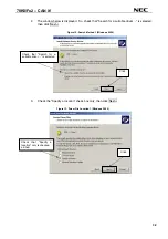
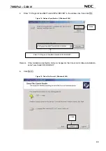
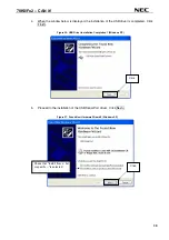
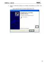
is connected, the USB driver needs to be installed on the host
machine. Please refer to the following
CHAPTER 8 SOFTWARE INSTALLATION
.
8. Software installation
The
78K0/Fx2 – CAN it!
package comes with several software demo packages:
•
IAR Systems Embedded Workbench for 78K0/78K0S, including C compiler, assembler, linker, librarian
and IAR C-SPY debugger
•
Device Files for
78K0/Fx2 – CAN it!
•
FPL FLASH programming software
•
Sample programs
The IAR Systems Embedded Workbenches and the FPL3 FLASH programming GUI must be installed on
your PC. For detailed installation hints, refer to the following chapters and to the corresponding
documentation of the IAR Embedded Workbench.
8.1 IAR Systems Embedded Workbench for 78K0/78K0S installation
To install the IAR Systems Embedded Workbench for 78K0/K0S including C-SPY debugger, select the
SETUP
program in the directory
\IAR Embedded Workbench 78K\ew78k\
of the CDROM. The setup
dialogues will guide you through the installation process.
8.2 Device file installation
To install the device files for the
78K0/Fx2 – CAN it!
in order to use the IAR C-SPY debugger, select the
SETUP
program in the directory
\Device Files\
of the CDROM. The setup dialogues will guide you
through the installation process.
8.3 FPL3 FLASH programming GUI installation
To install the FPL3 FLASH programming GUI select the
SETUP
program in the directory
\FPL3\
of the
CDROM. The setup dialogues will guide you through the installation process.
8.4 Sample program installation
To install the sample / demonstration programs for the
78K0/Fx2 – CAN it!
board select the
SETUP
program
in the directory
\SamplePrograms\
of the CDROM. The setup dialogues will guide you through the
installation process.
28


