background image

29

UDP
UDP is recommended for networks where there is extended latency from one end to the other. The nature of 

UDP means that it does not receive a confirmation of each packet being received successfully – vastly improving 

performance on busy networks. UDP can have some consequences f there are other issues on the network such as 

jitter or lost packets as it will not inherently re-sent a lost packet.

R-UDP (Reliable UDP)
This protocol bridges the performance of TCP and UDP. Compared to TCP, it reduces overall network load (allowing 

more NDI streams) by not requiring every packet to be ‘acknowledged’ by every receiver – has error correction 

built in for smoothness and reliability.

Multicast 
Multicast is especially useful for use-cases that require a single source to be received on multiple receivers 

simultaneously. Utilizing Multicast offloads the distribution of the NDI® A/V packets from the BirdDog P100 to the 

network infrastructure. You should take care to ensure your network is specifically configured to support Multicast 

as using it on an ill-prepared network can create unintended network problems. 

NDI Discovery

If  you  choose  to  use  a  NDI®  discovery  server,  you  can  configure  it  in  this  tab.  By  default,  NDI®  utilizes  mDNS 

(multicast Domain Name System) to create the zero configuration environment for discovery. Unless the network 

is specifically configured to not allow mDNS, NDI® sources will be discovered. 

The NDI® discovery service is designed to replace the automatic discovery NDI® uses with a server that operates 

as an efficient centralized registry of NDI® sources that requires much less bandwidth. Multiple servers can be 

specified for failover reduntancy. NDI® discovery server also helps with location of devices that reside on different 

subnets. The NDI® Discovery Server is available in the free 

NDI SDK

1. 

If you are using one or more NDI® Discovery Servers, click the ON button.

2. 

Enter a comma delimited list of the IP address(es) of your NDI® Discovery Server(s).

3. 

Click the APPLY button to save your changes.

System

Password Settings

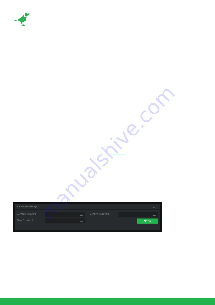
The BirdUI is secured by a user-selectable password. To make changes to any settings, you'll need to log in.

The default password is birddog (one word, lower case). It is recommended that the default password be changed, 

since the BirdUI grants full access to the camera configuration settings. 

You can change the password in the Password Settings tab.

1. 

Enter the current password.

2. 

Enter the new password. It is recommended that you change this password to retain administration rights to 

prevent unauthorized changes in a network environment where PTZ Keyboard is shared with other users (e.g. 

not private). Confirm the new password and click the APPLY button.

Summary of Contents for BirdDog P100

Page 1: ...USER GUIDE NDI 5 2022 ...

Page 2: ...cessories 6 Quick Start Guide 7 Basic Connections 7 Power Up 7 Computer say hello to P100 7 Basic Configuration 8 Camera Connections 11 Remote Controller 13 Powering P100 14 Thermal Management 14 Video Output 15 Audio Input Output 15 Using the Camera Menus 16 Camera Menus 17 White Balance Menu 17 Picture 1 Menu 18 Picture 2 Menu 18 Pan Tilt Zoom Menu 19 System Menu 19 ...

Page 3: ...he Infrared Remote Controller 24 Web Configuration Panel 25 Password Management 25 BirdUI Layout 26 Dashboard 27 Network 27 NDI Network Settings 28 System 29 System Update 30 Access Manager Configuration 30 System Reboot 30 AV Setup 31 NDI Encode Settings 31 CamControl 33 FreeD Tab 33 Preset Tab 33 Exposure Tab 34 White Balance Tab 34 Picture Tab 35 Color Matrix Tab 36 Scopes 37 Receiving NDI Vide...

Page 4: ...itial Setting Status Information 40 VISCA over IP Control 41 Setting the DIP Switches 42 Using RS 232 VISCA 44 Using RS422 VISCA 46 PELCO P D Keyboard RS485 Connection 49 Operating Multiple Cameras using RS 232 and 422 485 52 Camera Dimensions 53 Glossary 54 ...

Page 5: ... products or procedures described in the manual Best effort has been made to verify the integrity and correctness of the contents in this document but no statement information or recommendation in this manual shall constitute formal guarantee of any kind expressed or implied We shall not be held responsible for any technical or typographical errors in this manual The product appearance shown in th...

Page 6: ...of the FCC Rules These limits are designed to provide reasonable protection against harmful interference when the equipment is operated in a commercial environment This equipment generates uses and can radiate radio frequency energy and if not installed and used in accordance with the instruction manual may cause harmful interference to radio communications Operation of this equipment in a residen...

Page 7: ...s in your browser or PDF reader to increase the page size when viewing the diagrams to reveal much more detail First Step Firmware Upgrade Before you use your new P100 it s a good idea to upgrade to the lastest firmware We are always adding new features and improving the performance of our products so installing the latest firmware will provide you with the best user experience To upgrade the firm...

Page 8: ... mounting with E Flip function Control supports RS 232 control RS 422 485 control VISCA over IP NDI Control IR Remote Controller Presets store camera directions and image parameters Up to 6 presets on remote controller or 128 presets via protocol programming Image parameter setting restore with presets and quick access operation Supports Audio input Audio output with NDI streaming Power DC 12V PoE...

Page 9: ...bit network you have the potential for a streamlined interconnected video production environment With the introduction of NDI 5 you can now securely share network sources between remote sites anywhere in the world on a single network port Even a smartphone can be a NDI source Transitioning to NDI can also occur gradually Existing SDI or HDMI signals can easily be converted to an NDI stream and pip...

Page 10: ...o purchase these optional accessories Please browse to this page on our website for all your accessory needs 1x BirdDog P100 1x IR Remote Controller 3V CR2032 Coin Lithium Battery Required 1x Camera Power Adaptor 1x Bag of Camera Mounting Screws 1x USB to 3 5mm Audio Cable RS232 8 Pin Mini DIN to Phoenix Terminal Block Wall Mount Ceiling Mount RJ45 to RS422 Adaptor Cable ...

Page 11: ... port Power Up Once you ve made the power and Ethernet connections turn on the adapter power When first powered up the camera will perform it s initialization routine by rotating to the left and then centering again When this is finished the indicator light on the front of the camera will display green and occasionally amber and the camera is ready to be accessed Computer say hello to P100 Since w...

Page 12: ... list will display the image from your camera with the default automatic settings The BirdUI BirdDog cameras have a web interface BirdUI that is displayed by your computer browser and can be used to configure your camera remotely 1 Click on the gear icon on the bottom right of the Studio Monitor window 2 The Dashboard window is displayed To change settings type the default password birddog all low...

Page 13: ...ibility of video sources to viewers that are not part of the group If disabled the video source is public and viewable by any receiver on your network NDI Stream Name Give the output video stream of the camera a memorable name to make identification easier on NDI receiving devices NDI Audio You can choose to embed audio from the audio input connector into the NDI stream or mute it NDI Failover Sou...

Page 14: ...pplied IP address If you then use the camera for another job without a DHCP server your camera will always default to the known fallover IP address BirdDog Name You can give your camera a meaningful name to make identification easier when viewing NDI sources on a receiver such as a TriCaster vMix or Studio Monitor Be sure to make the name unique as no two devices on the network should have the sam...

Page 15: ...232 422 adaptor cable is provided 6 USB Port For MCU upgrade Used for audio in out USB port to 3 5mm audio jack adaptor included Audio format is stereo unbalanced line level 7 USB 3 0 Port TYPE B Used for USB UVC video and baseboard update 8 Power LED Indicator Turns green when the camera is connected to power outlet When the power is turned on it takes about 15 to 30 seconds to display the image ...

Page 16: ...e camera receives commands from the infrared remote controller 11 Tripod Mounting Holes 12 Fixed Mounting Holes For original wall ceiling mount bracket 13 Base DIP Switch Used for setting the camera configuration For details refer to Setting the DIP Switches ...

Page 17: ...l Home Home position Resolution reset 5 L R Direction Set Left and right orientation setting 6 Zoom Focus Far for objects further from the camera Near for objects closer to the camera 7 Auto Manual Focus 8 Back Light 9 Video Format Switching You can change the video format by keep pressing the button When video format is changed the camera would restart and the screen turns black for few seconds 1...

Page 18: ...ype4 supplied with the unit WARNING Do not attempt to manually move the camera head when the device is powered up Doing so may damage the camera Thermal Management Although the camera is equipped with a fan the entire enclosure is designed to dissipate heat The main processor is capable of operating up to 100º C 212º F Various factors can affect how much heat the camera will produce and it is norm...

Page 19: ...ideo will display on the monitor 3 Information of the camera initial setting status will display on the monitor for 5 seconds 4 You can set the displayed video format in the camera System menu SDI Signal The camera can simultaneously stream SDI video output with HDMI video output 1 Connect your camera to the SDI device display with an SDI cable USB Video Signal 1 Connect the camera to your USB dev...

Page 20: ...enter the sub menu of a selected item click either the button or the HOME button In the example below we are navigating between two sub menus of the Exposure main menu Sub menus can also be navigated vertically to select sub menu items 4 Once you ve navigated to a setting value use the buttons to increment or decrement the value 5 Press the MENU button to exit the menus NOTE When you are operating...

Page 21: ... you can adjust depending on your chosen exposure mode Gain Select the gain Speed Select the shutter speed Iris Select the iris setting Ex Comp Exposure compensation When MODE is set to FULL AUTO SHUTTER PRI or IRIS PRI setting EX COMP to ON allows exposure compensation levels to be set White Balance Menu WB Mode White balance mode Auto This mode computes the white balance value output using color...

Page 22: ...ide down for ceiling mounted cameras Select from upright mode OFF or ceiling mount ON Mirror Displays a mirror image of the video De flicker Turning this on can help reduce the image flicker that can occur if the camera frame rate is different to the frequency of the local electricity supply that is powering the scene lighting Picture 2 Menu Gamma Adjusts the gamma of the image WDR Wide dynamic ra...

Page 23: ...call movement speed Pan Dir Camera horizontal Left and right orientation setting Options are Normal or Invert Tilt Dir Camera tilt up and down orientation setting Options are Normal or Invert System Menu Pelco ID When using RS485 PELCO P D control set Camera ID to the controlled address This value is from 001 255 IR Receive Infrared Signal Reception When this is set to OFF the camera does not rece...

Page 24: ... value on some product models or the HOME button to confirm After confirmation press the HOME button again to restore it The camera will reboot by itself and the new video format is activated You can cancel by pressing the MENU button Depending on the video client software you are using some video software may need to be restarted to obtain the new video format NOTE The camera video format can als...

Page 25: ... whenever you press the button To set the remote to move the camera toward the opposite direction from that of the button you pressed press the 2 REV button while holding down the L R DIRECTION SET button NOTE The above setting only changes the control signal emitted from the infrared remote controller and does not change the setting of the camera itself Therefore repeat the setting for each infra...

Page 26: ...E The BACK LIGHT function is effective if MODE is set to FULL AUTO in the EXPOSURE menu of the camera Changing Resolution 1 Press the RESOLUTION button 2 Use the arrow keys to navigate the displayed menu 3 Press HOME to select 4 Screen will display CHANGING 5 Press MENU to exit Storing the Camera Settings in Memory Using Presets Using the preset function six sets of camera shooting conditions can ...

Page 27: ...u have stored your settings press any of the POSITION buttons 1 to 6 to recall those settings Cancelling the preset memory While holding down the RESET button press the POSITION button that you wish to delete NOTE When the power is turned on the camera starts with the settings stored in POSITION 1 When you are storing or cancelling the settings in one POSITION you cannot call up store or cancel th...

Page 28: ...r to the camera 1 2 or 3 2 Press the corresponding CAMERA SELECT button on the infrared remote controller 3 You can now operate the camera s specified by that number Each time you operate the camera s using the infrared remote controller the CAMERA SELECT button pressed in step 2 illuminates MENU POWER CAMERA SELECT CAMERA SELECT ...

Page 29: ...IP address the camera will reassign to the designated fallback address the default is 192 168 100 100 In order to access the BirdUI on a network which is configured to a different subnet change your computers IP address to match the BirdDog unit Once you gain access to the BirdUI choose your IP address to match the rest of the devices on your network For instructions on setting your computer s IP ...

Page 30: ...dress details fallback address timeout and camera network name as well as NDI specific network settings 3 System System admin functions such as updates password change designation of group access and camera reboot 4 AV Setup Full NDI encode management and audio settings 5 CamControl Exposure white balance picture and color settings 6 Scopes Settings for the Histogram Waveform RGB Parade and Vector...

Page 31: ... chroma subsample rate 6 System Details a Camera Name as set here b Network Details as set here c Online Status of the camera d MAC address and current firmware version of the camera Network Network Details Most computer networks provide for both automatic and manual configuration of network devices and the P100 can accommodate both Configuration Method Here you can set the network configuration t...

Page 32: ...make identification easier when viewing NDI sources on a receiver such as a TriCaster vMix or Studio Monitor Be sure to make the name unique as no two devices on the network should have the same name The name can be any combination of a z 0 9 and After renaming your camera navigate back to the System menu and click the REBOOT button The camera will re initialize and you ll be good to go NDI Networ...

Page 33: ...ame System to create the zero configuration environment for discovery Unless the network is specifically configured to not allow mDNS NDI sources will be discovered The NDI discovery service is designed to replace the automatic discovery NDI uses with a server that operates as an efficient centralized registry of NDI sources that requires much less bandwidth Multiple servers can be specified for f...

Page 34: ...haring with other cameras To upload a list 1 Click the CHOOSE FILE button to load your Remote IP List in UTF 8 encoded string format 2 Click the UPDATE button Do not upload a blank list NDI Group List Set the NDI group list NDI groups allow you to restrict communication to only devices that belong to the same NDI group NDI Groups can be very useful in larger environments to control visibility and ...

Page 35: ...ent for your networking infrastructure lower bandwidth or higher image quality for critical footage The scale allows you to select the range of 60 360 Mbps By setting Bitrate Management to NDI MANAGED the target bitrate will be set in accordance with the NDI standard By selecting MANUAL you are able to manually select a target bitrate Select MANUAL with care as you will need to account for the cap...

Page 36: ...tream Encoder Screensaver Assign a captured frame black frame or BirdDog logo as a screensaver Capture Screensaver Frame Click the CAPTURE button to capture the current frame for use as a screensaver Onboard Tally Enable the camera Tally lights NDI Genlock Source Select the NDI genlock source from the dropdown list NDI Failover Source NDI has a failover function where you can designate an alternat...

Page 37: ...ettings Reset Click this button to reset all image settings to their factory default FreeD Tab Enable or disable FreeD FreeD is a protocol for real time camera PTZ position query Any application that uses FreeD can use this data usually in a virtual environment where a physical camera move i e pan tilt zoom or iris change can trigger the virtual environment to follow that move in real time IP Addr...

Page 38: ...80i50 1080P25 or 720P50 shutter speed can be selected from the following 1 1 1 2 1 3 1 6 1 12 1 25 1 50 1 75 1 100 1 120 1 150 1 215 1 300 1 425 1 600 1 1000 1 1250 1 1750 1 2500 1 3500 1 6000 1 10K When video format is set to 720P30 1080i59 94 1080P29 97 720P59 94 1080P59 94 1080I60 1080P30 1080P60 or 720P60 shutter speed can be selected from the following 1 1 1 2 1 4 1 8 1 15 1 30 1 60 1 90 1 10...

Page 39: ...colors in the image Cam Color Temp Sets the color temperature of the image in degrees Kelvin Picture Tab Sharpness Adjusts the picture sharpness value from 0 to 15 Effect Select from Monochrome Image B W or Color image OFF Noise Reduction Can reduce the level of image noise Select 6 levels from OFF 1 5 MAX Flip Flips the image upside down for ceiling mounted cameras Select from upright mode OFF or...

Page 40: ...turated to the camera Color Hue The Color Hue option adjusts the temperature or phase in which any color is represented When looking at the color spectrum beyond the true color points Red Green Blue Cyan Magenta and Yellow there are areas where the colors transition to their neighboring color point Color Matrix controls allow you to adjust the color offset in a negative counter clockwise or positi...

Page 41: ... Waveform or RGB Parade scope the Histogram does not indicate the left to right physical position of the luminance values in the image Waveform The Waveform scope shows the distribution of luminance in the image as a waveform that ranges from zero at the lower horizontal line to 100 intensity at the upper horizontal line The left to right position of the values match their position in the image RG...

Page 42: ...ra from the dropdown list Once connected to P100 a configuration gear icon is displayed on the bottom right hand side of the video display providing shortcut access the BirdUI NewTek TriCaster Series NewTek TriCaster series devices allow several NDI sources to be received simultaneously the number of simultaneous connections depending on what model TriCaster you have To select P100 as a source on ...

Page 43: ...er connect and control your PTZ cameras IP Connection IP Port to Network Switch 1 Connect the camera NDI Ethernet port to a port in a Ethernet switch on your network The switch must provide PoE if you are not using the power adaptor 2 Connect the PTZ Keyboard s IP port to a port on the Ethernet switch or other connected switch on the same network subnet 3 Login to the web interface BirdUI of the c...

Page 44: ...guration a HDMI cable SDI video cable data cable and network cable is required To obtain these third party components or accessories consult the dealer where you bought your camera Camera Initial Setting Status Information Upon boot up the camera initial setting status will display on the monitor for 5 seconds 1 Camera PELCO ID for RS 485 control 2 Camera ID for IR Remote Controller 3 IR remote co...

Page 45: ...ing via VISCA over IP 1 Connect the network port on the camera to the network switch 2 Set the IP address and other network information appropriately to communicate on your network 3 Connect the VISCA over IP compatible controller to the network 4 Configure the controller to access the camera s IP address and VISCA over the IP port 5 The IP port within on your control must be set to 52381 to commu...

Page 46: ...n the orientation below Default Setting ON OFF OFF OFF OFF OFF OFF ON 1 Bit 1 3 Camera Address setting for VISCA protocol 2 Bit 4 Video Output Video Color Space When using HDMI output to display on HDMI device set the DIP switch B4 to OFF When using HDMI to DVI convertor to have DVI video output set the DIP switch B4 to ON 3 Bit 5 Reserved 4 Bit 6 RS 232 RS 422 BOTTOM LEFT RIGHT LEFT VISCA Address...

Page 47: ...Setting Baud Rate Setting 2400 bps 4800 bps 9600 bps Default 38400 bps 7 OFF ON OFF ON 8 OFF OFF ON ON Video Resolution 1080i59 94 1080p29 97 720p59 94 1080p59 94 Empty 1080i60 1080p30 1080p60 1080i50 1080p25 720p50 1080p50 Empty Empty 720p60 1 OFF OFF OFF OFF OFF OFF OFF OFF ON ON ON ON ON ON ON 2 OFF OFF OFF OFF ON ON ON ON OFF OFF OFF OFF ON ON ON 3 OFF OFF ON ON OFF OFF ON ON OFF OFF ON ON OFF...

Page 48: ...ol method Set the Baud Rate to the same setting as the keyboard you are using Set specific camera address that you want to control the camera for If you want to have the camera address to be automatically assigned by the VISCA controller set the camera DIP switch address to 0 2 Reboot the camera by turning it Off and On after the DIP switch has been set up correctly 3 Camera supports Daisy Chain c...

Page 49: ...ke a daisy chain multiple camera connection with a standard RS232 serial port controller as below CAT5 6 Network Cable 1 Orange White 2 Orange 3 GND Green White 4 TX Blue 5 RX Blue White 6 Green 7 Brown White 8 Brown 1 8 RS232 Serial port connection on controller side RS232 1 2 3 GND 4 TX 5 RX 6 7 8 GND TXD RXD 1 2 3 GND 4 TX 5 RX 6 7 8 ...

Page 50: ... DIP switch Set the RS422 control method Set the Baud Rate to the same Baud Rate setting as the keyboard Set the specific address for the controlled camera If you want to have the camera address to be automatically assigned by the VISCA controller set the camera DIP switch address to 0 2 Reboot the camera by turning it Off and On after the DIP switch has been set 3 Use the included RJ45 to RS422 c...

Page 51: ... 5 GND 4 T 3 T 2 R 1 R Keyboard 1 2 3 4 5 GND 6 RXD IN 7 RXD IN 8 TXD IN 9 TXD IN RS422 VISCA Daisy Chain Multiple Cameras Connection SONY Keyboard RX RX T X TX GND RX RX T X TX GND RX RX T X TX GND RX RX TX TX GND KEYBOARD CAM 1 CAM 2 CAM 7 SONY Keyboard Connection Camera 5 GND 4 TXD IN 3 TXD IN 2 RXD IN 1 RXD IN Keyboard 1 GND 2 RXD IN 3 RXD IN 4 TXD IN 5 TXD IN RS422 VISCA Daisy Chain Multiple ...

Page 52: ...ct connection between the camera and the controller by following the pin definition below Multicore Control Cable PTZ Keyboard RS422 Serial Port connection on controller side VCC CC45RS Extension cable RS422 adaptor included 5 R 4 R 3 T 2 T 1 GND CAT5 6 Network Cable RS422 Port 1 RX Orange White 2 RX Orange 3 GND Green White 4 Blue 5 Blue White 6 Green 7 TX Brown White 8 TX Brown 1 8 ...

Page 53: ...Reboot the camera by turning it Off and On after the DIP switch has been set up correctly 4 Use a PELCO P D compatible keyboard 5 Use preset 95 on the keyboard to display exit the camera OSD menu 6 Use the joystick and button OPEN or CLOSE to navigate OSD menu 7 To operate keyboard please refer to the user manual of the keyboard you are using 5 R 4 R 3 T 2 T 1 GND VCC CC45RS RJ45 TO RS422 485 CONT...

Page 54: ...eyboard 6 RS485 7 RS485 RS422 VISCA Daisy Chain Multiple Cameras Connection VISCA Keyboard RS485 PELCO P D Keyboard Connection RX RX TX TX GND RX RX TX TX GND RX RX TX TX GND 1 TDX IN 2 TDX IN CAM 1 KEYBOARD CAM 2 CAM 255 Multicore Control Cable PTZ Keyboard RS485 Serial Port connection on controller side VCC CC45RS Extension cable RS422 adaptor included 5 R 4 R 3 T 2 T 1 GND ...

Page 55: ...ware You need to match the communication speed Baud Rate between the camera and the joystick controller You cannot use the RS 232 connections while you are using the RS422 485 connection CAT5 6 Network Cable RS485 Port 1 RX Orange White 2 RX Orange 3 GND Green White 4 Blue 5 Blue White 6 Green 7 TX Brown White 8 TX Brown 1 8 5 R 4 R 3 T 2 T 1 GND VCC CC45RS RJ45 TO RS422 485 CONTROL CABLE ADAPTOR ...

Page 56: ...CA you can connect to 7 cameras Using RS 485 PELCO you can connect to 255 cameras Using RS 485 PELCO all camera addresses must be set up before the connection You can set the camera address by operating OSD menu or by setting the DIP switch on the bottom of the camera In this case you can use multiple control keyboards ...

Page 57: ...53 Camera Dimensions Unit mm ...

Page 58: ... rules formats and address scheme for exchanging datagrams or packets between a source computer or device and a destination computer or device LAN LAN Local Area Network is a network that connects computers and devices in a room building or group of buildings A system of LANs can also be connected to form a WAN Wide Area Network Mbps Mbps Megabits per second is a unit of measurement for data trans...

Page 59: ... Protocol is a network communications protocol UDP UDP User Datagram Protocol is an alternative protocol to TCP that is used when reliable delivery of data packets in not required VISCA VISCA is a camera control protocol used with PTZ cameras See also PELCO WAN WAN Wide Area Network is a network that spans a relatively broad geographical area such as a state region or nation White Balance White ba...

Page 60: ...WELCOME TO THE FUTURE ...

Page 61: ...birddog tv hello birddog tv ...

Reviews: