background image

Operation and Cleaning

3-36

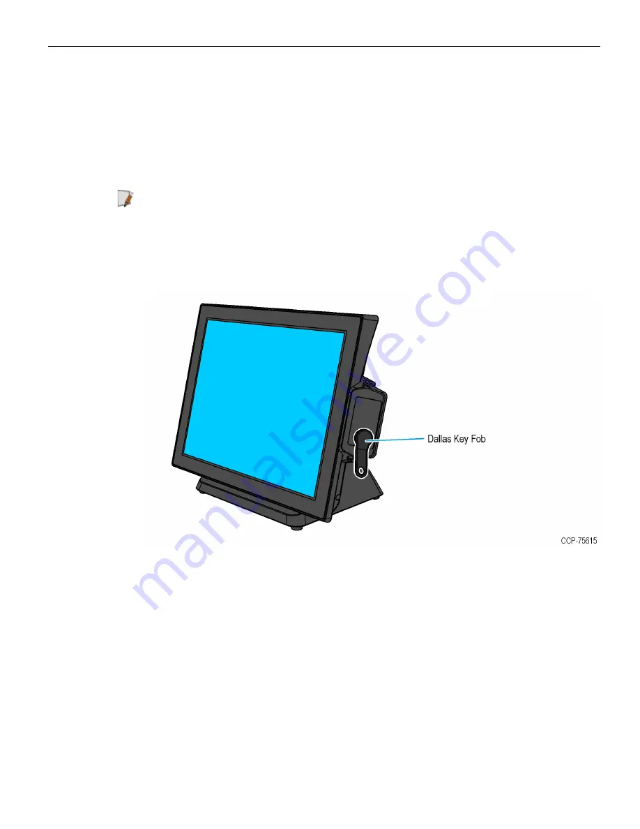
Dallas iButton Reader

The NCR EX15 POS (4505) offers a Dallas iButton Reader as a kit. It reads the unique
registration number or ID code of Dallas Touch Memory Buttons, which is used for
employee login to the POS software application.

The Dallas iButton Reader is mounted on the right side of the display and interfaces
through a USB connection in the display head.

Note:

For more information, refer to

EX15 Dallas iButton Reader Kit Instructions

(4505-K150).

Using the Dallas iButton Reader

Place the Key Fob on the round metal surface of the iButton Reader.

Summary of Contents for EX15 POS

Page 1: ...User Guide NCR EX15 POS 4505 Release 1 0 BCC5 0000 5295 Issue A...

Page 2: ...ucts as new technology components software and firmware become available NCR therefore reserves the right to change specifications without prior notice All features functions and operations described...

Page 3: ...ed batteries according to the manufacturer s instructions Attention Il y a danger d explosion s il y a remplacement incorrect de la batterie Remplacer uniquement avec une batterie du m me type ou d un...

Page 4: ...trician Improper connection of the equipment grounding conductor can result in a risk of electric shock The conductor with insulation having an outer surface that is green with or without yellow strip...

Page 5: ...not have access to a computer you may leave a voice message at 1 800 528 8658 USA or International 1 770 623 7400 When leaving a message please provide a phone number and or an email address so NCR ca...

Page 6: ...uipment location in the store Description of the problem including any system error codes error condition or guidance to the area of failure The NCR Agent will provide you with a work order number whi...

Page 7: ...ic Workplace 9 Installing the Terminal 10 Connecting the Cables 11 Routing the Cables 12 Connecting AC Power 14 Connecting to a Network 15 Disconnecting the Power Supply Cable 16 Installing the Transa...

Page 8: ...ng Touchscreens 34 Projected Capacitive Touchscreen 34 Using the PCap Touchscreen 34 Cleaning the Touchscreen 34 Magnetic Stripe Reader 35 Using the MSR 35 Care of Cards 35 Card Thickness 35 Dallas iB...

Page 9: ...vii Chapter 5 Initial Terminal Imaging Introduction 44 Imaging Procedure 44...

Page 10: ...viii Revision Record Issue Date Remarks A Nov 2018 First Issue...

Page 11: ...vers exceptional value and efficient performance in a sleek compact design It has a bezel free projected capacitive display that supports 10 point multi touch capability Powered by an Intel Celeron J1...

Page 12: ...0001 EX15 POS 15 PCAP 4GB Memory 128GB SSD POSReady 7 4505 2004 0002 EX15 POS 15 PCAP 4GB Memory 128GB SSD Windows 10 4505 2004 0003 EX15 POS 15 PCAP 4GB Memory No Media No OS Note Storage devices po...

Page 13: ...LAN Support 10 100 Gb Ethernet support RJ45 LAN connector on rear IO with link activity speed LEDs Operating Systems POSReady 7 64 bit Windows 10 64 bit Ports 3 USB 2 0 1 USB 3 0 1 eSATAp USB2 0 comb...

Page 14: ...more information refer to the Site Preparation Guide Operation Temperature 0 C to 40 C Storage Temperature 25 C to 70 C Humidity 10 to 90 non condensing Mounting Options Integrated Stand Wall Mount Se...

Page 15: ...erview 1 5 Mounting Configurations Integrated Stand Tilt Angle When mounted on the integrated stand the display may be tilted for the best viewing angle The angle can be adjusted within 15 to 90 degre...

Page 16: ...1 6 Product Overview Wall Mount...

Page 17: ...Product Overview 1 7 Label Locations...

Page 18: ...rd as a power disconnect device Do not permit any object to rest on the power cord Do not locate the EX15 POS where the power cord can be walked on Use a grounding strap or touch a grounded metal obje...

Page 19: ...ing when considering the terminal workplace Avoid direct glaring and reflective glaring light Locate the terminal in a controlled luminance surrounding When installed next to windows position the term...

Page 20: ...d with the standard Table Top Stand and how to connect optional peripheral devices For installation procedures for the other mounting options see their associated kit instructions The EX15 POS comes f...

Page 21: ...S 4505 Port Port Name Description A DC OUT 12 Vdc power output B DC IN 19 Vdc power input C COM COM 1 2 3 4 connectors D DK Cash Drawer output E E SATAp E SATA USB connector F USB 3 0 1 USB 3 0 connec...

Page 22: ...n 2 12 Routing the Cables 1 Pivot the display toward the back 2 Lay the terminal face down on a flat surface Caution Always use a soft material cloth foam to protect the display screen when placing th...

Page 23: ...of the stand and then connect them to their assigned ports For more information refer to Connecting the Cables on page 11 4 Position the cables on the back of the stand and then return the terminal to...

Page 24: ...may cause damage to the unit 1 Connect the Power Supply cable to the DC IN port on the terminal 2 Connect the AC Power Cord to the Power Supply and then to an AC outlet Caution Do not connect or disco...

Page 25: ...n business configurations connecting to a network may allow connection to the Internet To connect the EX15 POS terminal to a network connect the 10 100 1000 Ethernet cable to the LAN port on the termi...

Page 26: ...ly Cable connector locks into position when connected to the terminal It cannot be disconnected by simply pulling on the cable To disconnect the Power Supply Cable slide its overmold out from the DC I...

Page 27: ...C879 0040 to the printer and the other end to the Serial Adapter 1432 C825 0004 2 Connect the other end of the Serial Adapter to one of the COM ports on the EX15 3 Connect the Power Supply Cable to t...

Page 28: ...Hardware Installation 2 18 Installing the Cash Drawer The Cash Drawer can be connected to the Cash Drawer connector or to the transaction printer...

Page 29: ...he terminal supports a 2 drawer configuration with a Dual Cash Drawer Cable Connect this cable to the terminal or transaction printer cash drawer connector using the 24V Dual Cash Drawer Cable 1432 C8...

Page 30: ...an be connected to any of the USB ports of the EX15 terminal Note For more information on the handheld scanner refer to its documentations on the manufacturers site https www honeywellaidc com product...

Page 31: ...ices system settings and then reboots to continue setup Complete the System Setup This varies from OS to OS but the following is typical 2 The initial setup procedures are performed Starting Windows P...

Page 32: ...his section discusses about connector pinouts as seen from the IO row 19 Vdc Power Input Port Pin Diagram Pin Signal Name 1 GND 2 24V 3 GND 4 24V COM Port RJ50 Pin Diagram Pin Signal Name 1 NC 2 DCD 3...

Page 33: ...ion Cash Drawer Port Pin Diagram Pin Signal Name 1 GND 2 COIL DRIVER 3 SENSE 4 24V 12v 5 COIL DRIVER 2 6 GND e SATAp Port Pin Diagram Pin Signal Name 1 USB VBus 2 USB D 3 USB D 4 USB GND 5 GND 6 A 7 A...

Page 34: ...t Pin Diagram Pin Signal Name 1 VBUS 2 D 3 D 4 GND 5 Rx 6 Rx 7 GND 8 Tx 9 Tx USB 2 0 Port Pin Diagram Pin Signal Name 1 VBUS 2 D 3 D 4 GND Network Pin Diagram Pin Signal Name 1 BI_DA 2 BI_DA 3 BI_DB 4...

Page 35: ...2 25 Hardware Installation VGA Port Pin Diagram Pin Signal Name 1 RED 2 GREEN 3 BLUE 4 RES 5 GND 6 RGND 7 GGND 8 BGND 9 KEY 10 SGND 11 ID0 12 SDA 13 HSYNC or CSYNC 14 VSYNC 15 SCL...

Page 36: ...age based on the voltage requirement of the peripheral to be attached COM 1 By BIOS setting only For more information refer to Setting the Serial Port COM 1 Voltage on page 42 COM 2 3 4 By jumper sett...

Page 37: ...re Installation Serial Adapter Cable Pinouts RJ50 to DB9 DB9 port is available through the serial adapter cable RJ50 Pin Signal Name DB9 Pin 1 VCC 9 2 GND 5 3 DTR 4 4 CTS 8 5 TX 3 6 RTS 7 7 RX 2 8 DSR...

Page 38: ...Hardware Installation 2 28 Accessing the Jumpers To access the jumpers follow these steps 1 Removing the Stand on the next page 2 Removing the Touch and LCD Assembly on page 31...

Page 39: ...back 2 Lay the terminal face down on a flat surface Caution Always use a soft material cloth foam to protect the display screen when placing the terminal face down 3 If the EX15 POS is installed with...

Page 40: ...Hardware Installation 2 30 4 Remove the four screws that secure the stand to the back of the display 5 Remove the stand and lay it down on a flat surface...

Page 41: ...to Removing the Stand on page 29 Note If the EX15 POS is installed with a Customer Display disconnect the Customer Display Cables before removing the stand 2 Remove the four screws on the back cover...

Page 42: ...the Touch and LCD Assembly rotate towards the back and place right beside the unit Caution At this point the Touch LCD Backlight LVDS and Speaker cables are still connected to the motherboard To avoid...

Page 43: ...lation 5 When replacing the Touch and LCD Assembly and the Motherboard disconnect the following cables from the motherboard When servicing other components it is not required to disconnect the cables...

Page 44: ...ve surface is not directly touched and does not wear off by normal use Since most surface contamination do not cause interference to the touchscreen the NCR EX15 POS 4505 can be used in public or seve...

Page 45: ...mounted on the right side of the display Using the MSR Swipe the card through the slot in the MSR in a quick and steady movement The magnetic stripe must be facing left and with the stripe in the slot...

Page 46: ...ttons which is used for employee login to the POS software application The Dallas iButton Reader is mounted on the right side of the display and interfaces through a USB connection in the display head...

Page 47: ...ticks which is used for employee login to the POS software application The Addimat Key Reader is mounted on the right side of the display and interfaces through a USB connection in the display head No...

Page 48: ...any strong dis solvent Do not use thinner or benzene abrasive cleaners or compressed air Warning Do not use any other types of cleaners such as vinegar solvents degreasers or ammonia based cleaners Th...

Page 49: ...and to make changes to their values To select highlight options and menu screens use the arrow keys To select a submenu use the Enter key To exit from a submenu use the Esc key To change field values...

Page 50: ...4 40 BIOS Setup Setting the LCD Brightness 1 Select Advanced Video Configuration...

Page 51: ...BIOS Setup 4 41 2 Select Brightness Control Level and then select a brightness level...

Page 52: ...4 42 BIOS Setup Setting the Serial Port COM 1 Voltage 1 Select Advanced S10 FINTEX F81866A...

Page 53: ...BIOS Setup 4 43 2 Select Voltage Selector and then select OK...

Page 54: ...nect the USB flash drive to the target terminal that you wish to image 2 Connect a USB keyboard to the terminal 3 Power on the terminal and boot from the USB Flash Drive This can be done by pressing F...

Reviews: