EPC4 Quick Reference Guide
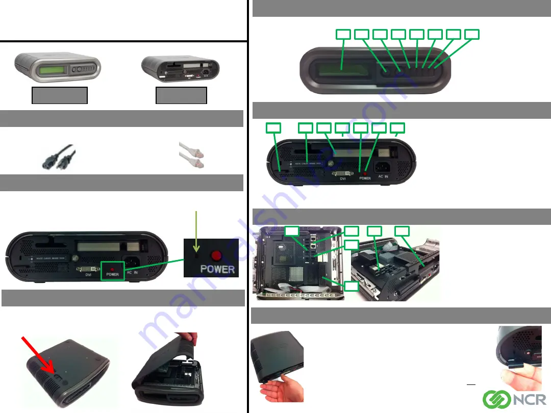
Graphical Overview
Front View
Rear View
Accessories Included
1 - 6ft (2m) Power Cable 90
°
(U.S. Models Only)
1 - 15ft (5m) Network Cable
4
– Power LED
Solid Red = AC plugged in but
not powered on
Solid Blue = Booting
Solid Green = After boot up
5
– Status LED
Solid Red = Initial
Solid Green = After boot up
6
– HDD LED
Blinking Blue = Activity
7
– Network 1 LED
Blinking Orange = Activity
8
– Network 2 LED
Blinking Orange = Activity
Internal Ports and Slots
1 –
2x Network LAN 10/100/1000
Port, not powered
2 –
4 x Serial Port RS232
3
– 2x Powered Serial Ports RS232
+12V/500mA each on RTS
4
– 4 x USB Ports +5V/500mA each
5
– PCI-e Expansion Slot
6
– SSD, MO-297 SATA 3.0Gb/s
Lock / Secure Enclosure
Recovery Utility
Pressing the Recovery Button on the rear of the unit will cause the EPC4
to boot to its Recovery Mode. This operation will automatically run a
check disk process to attempt to resolve any problems with the disk or
file system and then reboot into Normal Mode. A log of any changes will
be created by the check disk process.
Open Enclosure To Access Internal IO Ports
1
2
3
4
5
6
7
8
1
4
2
3
6
7
5
1
2
3
4
5
6
• To open enclosure, pull / push enclosure open latch toward the front IO.
• While the open enclosure latch is in the forward position, separate bottom and top housing.
• With EPC4 enclosure closed, pull out lock latch until “Locked” is
displayed
• Use one of the following to secure the device
• Standard Pad lock with a bolt diameter no less than .200” and no
greater than .280”
• Tamper Evident Zip Tie
• Kensington Lock
• Ensure Kensington lock is inserted through the rear IO and into the
Lock Latch
Back Panel Buttons and Ports
Front Panel Buttons and LED’s
1
– LCD Display
2
– LCD Display Control: NEXT
3
– LCD Display Control: SELECT
1 –
Power Socket 110-220V 50-60Hz
2
– Power On/Off Button
3
– Recovery Utility Button
4
– DVI Port *
5
– PCI-e Slot (Modem Optional)
6
– Lock Latch
7
– Cable Retention (Cables must route behind
door to be retained)
NCR P/N 497-0476345
Rev C
* Note: The DVI port should only be used for setup, maintenance and troubleshooting. It is not intended for use
during normal operation.


