Installation Guide
|
Comfort Pack T Series
with up to
95% Gas Heat
17
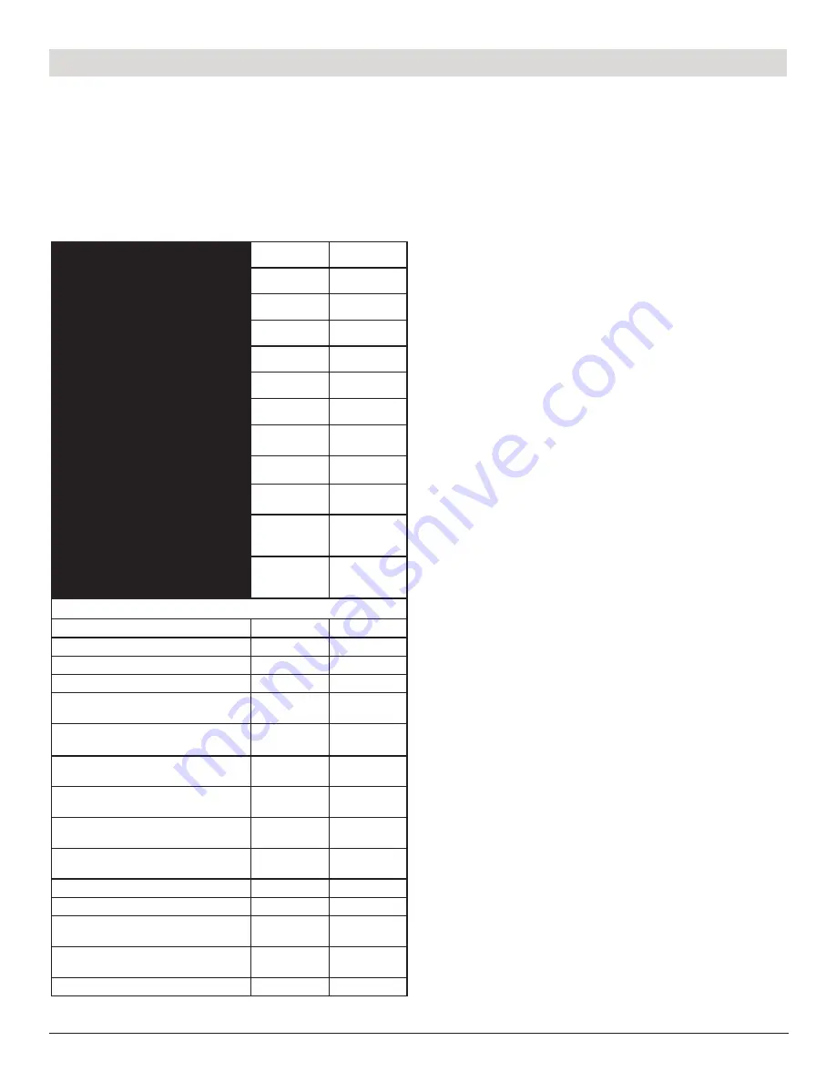
Gas Furnace Specifications
Gas Heat
– The cabinet includes a gas furnace with integral flue
duct, direct spark ignition, safety controls, and operating controls.
The installation of the unit and gas piping must be in accordance
with local codes.
Gas Valve Setting 3.5
"
W.C.
HEAT MODULE
CHS0043
CHS0050
INPUT BTUH (NG)
43,000
50,000
OUTPUT BTUH (NG)
40,850
47,500
INPUT BTUH (LP)
35,000
50,000
OUTPUT BTUH (LP)
33,250
47,500
MAXIMUM EXTERNAL STATIC PRESSURE
.4" W.C
.4" W.C
INLET PRESSURE (NG)
7.0" W.C.
7.0" W.C.
MANIFOLD
PRESSURE (NG)
3.5" W.C.
3.5" W.C.
INLET PRESSURE (LP)
11" W.C
11" W.C
MANIFOLD
PRESSURE (LP)
10" W.C
10" W.C
DISCHARGE
TEMPERATURE
RISE RANGE
35°F to 65°F
40°F to 70°F
BLOWER SPEED
SETTING
Med. High
High
MODEL SIZE
43
50
ORIFICE SIZE N.G.
#50
#47
ORIFICE SIZE L.P.
#60
#56
INDUCER ORIFICE SIZE
0.62
0.81
ROLLOUT LIMIT SIZE
(Manual Reset)
210
°
F
210
°
F
ROLLOUT LIMIT SIZE
(Maximum Allowance)
235
°F
235
°F
Main Air Limit Size
(Auto Reset)
140/-40
°
F
140/-40
°
F
Inducer Limit Size
(Manual Reset)
160
°
F
160
°
F
Nominal
Temperature Rise
50
°
F
55
°
F
Allowable Air
Temperature Range
135-165
140-170
CO2% - Acceptable Range
6 to 7
6 to 7
CO Air Free - PPM
0-200
0-200
Collector Box
Pressure Switch
-0.3+/-0.05
-0.6+/-0.05
Inducer Pressure
Switch
-0.9+/-0.05
-0.7+/-0.05
Stack Temperature
80-140
80-140
Sequence of Operations (Gas Heat)
1. Call for Heat
– The thermostat sends a call for heat therefore
energizing the “white” wire to the control board. The control checks
to see that the limit switch is closed and the pressure switch is
open. If the limit switch is open, the control responds as defined
in the “Limit Switch Operation - page 22”. If the pressure switch is
closed, the control will do four flashes on the green LED and wait
indefinitely for the pressure switch to open. If the pressure switch
is open, the control proceeds to
(2.) Pre-purge.
2. Pre-purge
– The control energizes the venter motor and waits for
the pressure switch to close. If the pressure switch does not close
within 240 seconds of the venter motor energizing, on 3 attempts,
the control green LED will flash two times and will enter a soft lock
out. When the pressure switch is proven closed, the control begins
the pre-purge time. If flame is present any time while in pre-purge,
the pre-purge time is restarted. If flame is present long enough to
cause lockout, the control responds as defined in “Undesired Flame
- page 22”. The control runs the venter motor for a 30 second pre-
purge time, then proceeds to the (
3.) Ignition Trial Period
.
3. Ignition Trial Period
– The control energizes the spark
and main gas valve. The venter remains energized. If flame is
sensed during the first 10 seconds, the spark is de-energized
and the control proceeds to
(4.) Heat Blower On Delay
. If flame
has not been sensed during the first 10 seconds, the control
de-energizes the spark output and keeps the gas valve energized
for an additional one second flame proving period. If flame is not
present after the flame proving period, the control de-energizes
the gas valve and proceeds with ignition re-tries as specified in
“Ignition Retry - page 18”. If flame is present, the control proceeds
to the
(4.) Heat Blower On Delay
4. Heat Blower On Delay
– The control waits for 20 seconds from
the time the gas valve opened and then energizes the blower motor.
The gas valve and venter motor remain energized. The control
proceeds to
(5.) Steady Heat.
5. Steady Heat
– The control continuously monitors to the
safeties (high limit, roll-out, and pressure) for open switches,
flame sensor for proving, and the thermostat for a call for
heat. When the thermostat call for heat is removed, the control
de-energizes the gas valve and begins
(6.) Post-purge
and
(7.) Blower Off Delay
.
6. Post-purge
– The venter motor output remains on for a
30-second post-purge period after the thermostat is satisfied.
7. Blower Off Delay
– The blower motor is de-energized after a
blower off delay 120 seconds factory setting (field adjustable, see
page 15 or 37). Timing begins when the thermostat is satisfied.
Summary of Contents for Comfort Pack CP9 T Series
Page 2: ...2...

