background image

SECTION 4 – ENGINE OPERATION

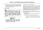
WARNING

To prevent personal injury or death, do not
attach jumper cable to the negative (-) dead
battery terminal. This can cause sparks and an
explosion.

5.

Connect one end of the second jumper cable to the negative
(-) terminal of the booster battery and the other end to
chassis frame of the vehicle with the dead battery.

6.

Start engine in vehicle that has the charged battery.

7.

Start engine in vehicle that has the dead battery.

WARNING

To prevent personal injury or death, always
disconnect jumper cable from negative contacts
first.

8.

Disconnect jumper cable from negative terminal and chassis
frame.

9.

Disconnect jumper cable from positive battery terminals or
one terminal and jump start stud.

Operation

SUGGESTED WARM-UP TIME

NOTE: Before applying a load or increasing speed above
1,000 rpm, warm up engine for a minimum of 5 minutes at
or below 1,000 rpm. The warm-up period allows lubricating
oil to establish a film between moving parts.

After allowing the engine to warm up for 5 minutes, begin
operating the vehicle at reduced engine speeds and load
until it reaches operating temperature.

Once operating

temperature is reached, begin normal operation. The Cold
Ambient Protection (CAP) system aids in engine warm up
and maintains engine heat during extended idling periods.
See Cold Ambient Protection (CAP) (page 54).

IDLE SPEED

WARNING

To prevent personal injury or death, provide
ventilation when operating an engine in a closed
area. Inhalation of exhaust gas can be fatal.

Low idle speed forMaxxForce

®

DT, 9, & 10 Diesel Engines is 700

rpm (nonadjustable). If the engine coolant temperature is below
70 °C (158 °F), the Engine Control Module (ECM) will adjust the
low idle speed from 700 rpm to a maximum of 875 rpm. High
idle speed is a nonadjustable factory setting.

Page 49

Summary of Contents for MaxxForce 10

Page 1: ...OBD US Canada Mexico 4328100R3 March 2015 MaxxForce DT 9 10 Engine Operation and Maintenance Manual Navistar Inc 2701 Navistar Drive Lisle IL 60532 USA 2015 Navistar Inc All rights reserved All marks...

Page 2: ...e neither downloaded nor retrieved except by the vehicle s registered owner or in the alternative by another individual or entity authorized by the registered owner e g International Dealer who may ne...

Page 3: ...and Responsibilities 9 California Emission System Warranty 9 Warranty Period 9 Required Maintenance 10 Warranty Repairs and Service 10 Recommended Maintenance or Repair Parts 10 Emergency Repairs 10...

Page 4: ...Ultra Low Sulfur Diesel ULSD 29 Unacceptable Fuel and Blends 29 Acceptable Fuel Blends 30 Use of Higher Biodiesel Fuel Blends B6 to B20 30 Unsafe Practices 31 Engine Oil 31 Engine Oil Quality and Ser...

Page 5: ...Switches 43 Engine Brake ON OFF Switch 43 Engine Exhaust Brake ON OFF Toggle Switch 43 Air Cleaner Restriction Indicator 44 SECTION 4 ENGINE OPERATION Preoperation Checklist 45 Priming the Fuel System...

Page 6: ...RES Maintenance Schedule 57 Service Procedures 60 Oil Level 60 Coolant Level 61 Water Separator 62 Charge Air Cooler CAC 64 External Leakage 64 Air Cleaner Restriction 64 Engine Oil and Filter 65 Cent...

Page 7: ...lant ELC Extender 82 Crankcase Pressure 83 Turbochargers 83 Cleaning Diesel Particulate Filter 83 Service Cooling System 83 SECTION 6 LONG TERM STORAGE General Information 87 SECTION 7 SERVICE RECORDS...

Page 8: ......

Page 9: ...s revised periodically Use only up to date service information To order technical service literature contact your dealer All marks are trademarks of their respective owners About the Manual This manua...

Page 10: ...FOREWORD Page 2...

Page 11: ...tion of the engine Warning Caution and Note Warning A warning describes actions necessary to prevent or eliminate conditions hazards and unsafe practices that can cause personal injury or death Cautio...

Page 12: ...em before removing panels housing covers and caps If an engine is not safe to operate tag the engine and ignition key Fire Prevention Make sure charged fire extinguishers are in the work area NOTE Che...

Page 13: ...systems under pressure Follow approved procedures only Fuel Do not over fill the fuel tank Over fill creates a fire hazard Do not smoke in the work area Do not refuel the tank when the engine is runni...

Page 14: ...SAFETY INFORMATION Page 6...

Page 15: ...d to the first retail purchaser REQUIRED MAINTENANCE As the vehicle owner you are responsible for all required maintenance described in this manual Navistar recommends that you retain all maintenance...

Page 16: ...do not exceed manufacturer s suggested retail price Labor charges based on manufacturer s recommended time allowance and geographic hourly rate Replaced parts and paid invoices must be given to your...

Page 17: ...ifornia Emission System Warranty WARRANTY PERIOD The California Air Resources Board and Navistar Inc are pleased to explain the emission control system warranty on your 2014 heavy duty diesel engine I...

Page 18: ...and diagnostics Warranty repairs should be completed in a reasonable time not to exceed 30 days Navistar Inc may deny you warranty coverage if your vehicle or a part has failed due to abuse neglect i...

Page 19: ...nsibility for an extended warranty is shared between the owner and the manufacturer the emission warranty shall also be shared in the same manner as specified in the warranty agreement New vehicles an...

Page 20: ...engine or commercial loss Vehicles with an altered or disconnected odometer or hourmeter when mileage or hours cannot be determined WARRANTY RIGHTS AND RESPONSIBILITIES Navistar assures that the emiss...

Page 21: ...ader On the engine emission label on the valve cover Engine Serial Number Examples MaxxForce DT 466HM2U3300001 MaxxForce 9 and 10 570HM2U3300001 Engine Serial Number Codes 466 Engine displacement 570...

Page 22: ...e family model and displacement Advertised brake horsepower and torque rating Emission family and control systems Valve lash specifications Engine serial number EPA EURO and reserved fields for specif...

Page 23: ...Force DT engines MaxxForce 9 and 10 engines 7 6 L 466 in3 9 3 L 570 in3 Compression ratio MaxxForce DT engines MaxxForce 9 and 10 engines 16 9 1 16 5 1 Stroke MaxxForce DT engines MaxxForce 9 and 10 e...

Page 24: ...ation oil pressure at operating temperature with SAE 10W 30 oil Low idle High idle 15 psi 103 kPa minimum 50 psi 344 kPa minimum Idle speed no load 700 rpm 50 nonadjustable Thermostat operating temper...

Page 25: ...ng warm up The IAH system will initially illuminate the WAIT TO START lamp When the lamp turns off the engine can be started Crankcase Assembly The camshaft is supported by four insert bushings presse...

Page 26: ...option The pad mounting design of the alternator and refrigerant compressor brackets provide easy removal and improved durability Electronic Control System An Engine Control Module ECM monitors and c...

Page 27: ...e exhaust to meet tailpipe emission requirements The AFT system traps particulate matter soot using a Diesel Particulate Filter DPF The trapped particulate matter is then rendered to ash by heating th...

Page 28: ...N public supports the following functions Transmission of engine parameter data Transmission and clearing of DTCs Diagnostics and troubleshooting Programming performance parameter values Programming e...

Page 29: ...Coolant Heater A coolant heater is available to raise the temperature of the coolant surrounding the cylinders for improved performance during cold weather startups Cruise Control The ECM controls the...

Page 30: ...iary devices Customer programmable parameters within the Engine Control Module ECM provide in cab engine speed control related options that can be adjusted to suit the customer s needs Choosing whethe...

Page 31: ...the maximum accelerator controlled vehicle speed Service Interval The service interval feature is designed to provide a visual reminder to the operator that the engine oil change interval has expired...

Page 32: ...5 HP and above 4 Turbocharger air inlet duct 5 High pressure turbocharger outlet 6 Exhaust brake valve assembly 7 Valve cover 8 Exhaust emission label location 9 Air and Exhaust Gas Recirculation EGR...

Page 33: ...Water outlet tube assembly 3 Deaeration hose elbow 4 Air and Exhaust Gas Recirculation EGR mixer duct 5 EGR valve 6 Oil level gauge 7 Front cover 8 Fan drive pulley 9 Vibration damper assembly 10 Wate...

Page 34: ...el pump fuel strainer location 2 Fuel filter assembly 3 Oil level gauge 4 Exhaust Gas Recirculation EGR valve 5 Air and EGR mixer duct 6 Intake manifold 7 Engine Control Module ECM 8 Oil pan drain plu...

Page 35: ...ehicle heater port 7 Water supply housing refrigerant compressor mount 8 Alternator bracket 9 Crankcase breather outlet tube 10 Crankcase breather assembly with turbine 11 Exhaust Gas Recirculation EG...

Page 36: ...aust Gas Recirculation EGR mixer 2 Exhaust brake valve 3 Cylinder head 4 Turbo air inlet duct 5 EGR crossover tube assembly 6 Rear engine mounting bracket 2 7 Flywheel housing 8 Flywheel 9 Injector fe...

Page 37: ...content 0 0015 mass or 15 ppm maximum These specifications are included in the standard under the designation No 2 D S15 fuel and No 1 D S15 fuel Grade No 1 D fuel is a lighter fuel with higher volati...

Page 38: ...s Quality biodiesel blends up to B5 should not cause engine or fuel system problems USE OF HIGHER BIODIESEL FUEL BLENDS B6 TO B20 Standard ASTM D7467 08 covers the specifications for blends between 6...

Page 39: ...asohol or alcohol with diesel fuel An open heat source spark cell phone or electronic device can ignite these fuel mixtures This creates a fire hazard and possible explosion CAUTION To prevent engine...

Page 40: ...tain performance and durability of aftertreatment systems meeting 2007 and beyond diesel emission regulations API CI 4 oils are allowed in diesel engines that meet these regulations Use of the CI 4 en...

Page 41: ...pe III is the standard factory fill for the cooling system The coolant should minimally meet ASTM D6210 Standard Specification for fully Formulated Glycol Base Engine Coolant for Heavy Duty Engines EL...

Page 42: ...tion of the coolant Coolant color should be a reddish orange clear not cloudy Coolant must not have floating debris or visible oil Contamination of ELC with other coolant products will not be obvious...

Page 43: ...describe indicator lamps for the drivetrain chassis components or cab interior See the Vehicle Operator Manual Warning Lights Warning lights signal when a reading is outside preset limits Warning lam...

Page 44: ...down timer will turn the engine off in 30 seconds See Engine Idle Shutdown Timer page 51 for further information Maintenance Lamp Figure 13 Maintenance Lamp The Maintenance lamp will illuminate in con...

Page 45: ...ditions It is safe to drive the vehicle However if the lamp continues to light or remains on contact an authorized service provider immediately to have the problem corrected RED Stop Lamp RSL Figure 1...

Page 46: ...licable Vehicle Operator Manual Diesel Particulate Filter DPF Indicator Figure 17 DPF Indicator The DPF indicator operates at three different levels Level One The DPF indicator will illuminate solid Y...

Page 47: ...ing and an alarm will beep continuously while the ignition is on This indicates the exhaust filter is full and engine performance is limited Pull the vehicle safely off the roadway and start Parked Re...

Page 48: ...the ignition switch is turned to ON Normal engine operating temperature is 96 C 205 F CAUTION To prevent engine damage do not operate engine above 112 C 234 F this may cause internal damage The indica...

Page 49: ...low acceptable levels Shut down the engine immediately if the lamp and alarm are activated Contact an authorized service provider immediately to have the problem corrected Lubrication Oil Pressure Lub...

Page 50: ...SECTION 3 INSTRUMENTS INDICATORS AND SWITCHES Oil Temperature Gauge Figure 21 Oil temperature gauge The engine oil temperature gauge indicates the operating oil temperature of the engine Page 42...

Page 51: ...ine brake ON OFF switch Turns engine compression brake ON or OFF ENGINE EXHAUST BRAKE ON OFF TOGGLE SWITCH Figure 23 Exhaust brake toggle switch The exhaust brake toggle switch turns engine exhaust br...

Page 52: ...indicator should be tested periodically using a master vacuum gauge to ensure a correct calibration Air Restriction Indicator Operation The yellow position indicator progressively fills the window as...

Page 53: ...ion The operator should fully understand the use and function of all controls and instruments 1 Check cooling system level Figure 25 Oil level gauge typical CAUTION To prevent engine damage do not ove...

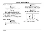
Page 54: ...ing is closed and fuel filter caps are on tight 3 Turn ignition switch to ON for approximately 60 seconds allowing electric fuel pump to prime the fuel system Starting the Engine WARNING To prevent pe...

Page 55: ...The ignition switch will return to ON and the engine will continue to run 6 With the transmission in neutral release clutch pedal if equipped 7 Until oil pressure is achieved the engine will not accel...

Page 56: ...away from battery Protect against inhaling hydrogen gas fumes from battery Use a 12 volt system with a negative ground Do not exceed 16 0 volts if the ignition switch is turned to OFF ACC or ON during...

Page 57: ...g speed above 1 000 rpm warm up engine for a minimum of 5 minutes at or below 1 000 rpm The warm up period allows lubricating oil to establish a film between moving parts After allowing the engine to...

Page 58: ...UST AFTERTREATMENT SYSTEM The engine and vehicle exhaust piping includes an Aftertreatment System to capture soot and other particulates before they exit the exhaust pipe The soot is captured by the D...

Page 59: ...ll be severely limited and a Parked Regeneration will be required to prevent engine shut down When a Regen occurs do the following The operator must park the vehicle and then perform the Regen as requ...

Page 60: ...tection CAP will not function ENGINE IDLE SHUTDOWN TIMER CALIFORNIA STANDARD GOVERNMENT REGULATION State and local regulations may limit engine idle time The vehicle owner or operator is responsible f...

Page 61: ...lutch pedal switch fault is detected manual transmissions if equipped with a clutch switch Shift selector is moved from neutral automatic transmissions If the IST is enabled the Cold Ambient Protectio...

Page 62: ...when ambient air temperature is below 0 C 32 F coolant temperature is below 65 C 149 F and engine has been idling at no load for over 5 minutes Engine speed will ramp up to 1 400 rpm and will maintai...

Page 63: ...system problems when the Malfunction Indicator Lamp MIL illuminates When the MIL illuminates bring the vehicle in for service at the next available opportunity The HD OBD system does not change the wa...

Page 64: ...ring full throttle 4 When approaching a hill press accelerator smoothly to start the upgrade at full power Downshift to maintain maximum vehicle speed DOWNHILL OPERATION CAUTION To prevent engine dama...

Page 65: ...l Service Operation See service procedures in this section for more information Before Engine Operation Check engine oil level Check coolant level Drain water separator 1 Inspect Charge Air Cooler CAC...

Page 66: ...100 hours 15 898 liters 4 200 gallons of fuel Change fuel filter Clean or change fuel strainer Annually Inspect electrical system 120 000 miles 193 000 km 5 000 hours Inspect vibration damper Adjust e...

Page 67: ...rmation 200 000 miles 322 000 km 30 months 6 000 hours Cleaning Diesel Particulate Filter DPF 2 300 000 miles 500 000 km 5 years 12 000 hours Service cooling system 3 1 Drain water separator Daily 2 R...

Page 68: ...ransmission to park or neutral set parking brake and install wheel chocks before doing diagnostic or service procedures OIL LEVEL Service Interval Before Engine Operation 1 Park vehicle on level groun...

Page 69: ...on to park or neutral set parking brake and install wheel chocks before doing diagnostic or service procedures Service Interval Before Engine Operation Extended Life Coolant ELC 50 50 Premix is the st...

Page 70: ...50 Premix to the correct coolant level midpoint of ADD and MAX 4 Install and tighten coolant tank cap until the plastic cap clicks or the metal caps runs up against the detent WATER SEPARATOR Service...

Page 71: ...fuel flow 4 Turn water drain valve to open and allow water fuel mixture to drain Continue draining until only fuel is draining NOTE Fuel will only drain from the water drain valve as long as the elect...

Page 72: ...Before starting engine remove any debris blocking the core EXTERNAL LEAKAGE Service Interval Before Engine Operation WARNING To prevent personal injury or death shut down engine set parking brake and...

Page 73: ...r damage or distortion Install new housing if necessary 4 Install a new air filter element 5 Push reset button on air restriction indicator The yellow indicator will return to zero ENGINE OIL AND FILT...

Page 74: ...han 8 5 1 000 hours 30 000 miles 48 300 km 4 5 to 8 5 800 hours See Figure 33 Less than 4 5 600 hours 12 500 miles 20 117 km MaxxForce DT 9 and 10 Diesel Engines With Greater Than 230 Horsepower Witho...

Page 75: ...other contaminated materials such as filters rags in accordance with applicable regulations Recycle or dispose of engine fluids filters and other contaminated materials according to applicable regulat...

Page 76: ...nd recycle or dispose of according to applicable regulations 10 Lubricate new oil filter gasket with clean engine oil CAUTION To prevent engine damage install the correct oil filter for the engine app...

Page 77: ...n the upper half of the crosshatched operating range on oil level gauge CENTRIFUGE FILTER IF EQUIPPED Service Interval based upon fuel consumption and specific engine application The centrifuge filter...

Page 78: ...t let engine fluids stay on your skin Clean skin and nails using hand cleaner and wash with soap and water Wash or discard clothing and rags contaminated with engine fluids 1 Park the vehicle on level...

Page 79: ...INTENANCE SCHEDULE AND SERVICE PROCEDURES Figure 33 Centrifuge filter assembly 1 Cover assembly 2 Band clamp handle 3 Body assembly 4 Band clamp Figure 34 Centrifuge rotor 1 O ring 2 Rotor 3 Body asse...

Page 80: ...cover and body flanges Engage the tee bolt and turn the band clamp handle and tighten securely 13 Start the engine and check all connections for leaks If no leaks are observed shut down engine If leak...

Page 81: ...dition of all drive belts For any of the following conditions install a new belt Excessive wear Missing material Grease or oil contamination Over three cracks per inch in a belt rib Belt Removal 1 Att...

Page 82: ...bar clockwise and install the belt over the auto tensioner pulley and other pulleys 3 Slowly release the breaker bar the auto tensioner automatically adjusts 4 Remove the breaker bar Air Intake Pipin...

Page 83: ...60 water 12 F 24 4 C 50 Concentrate and 50 water 34 F 36 7 C 60 Concentrate and 40 water 62 F 52 0 C 67 Concentrate and 33 water 95 F 70 6 C For vehicles operating in extremely cold climates a coolan...

Page 84: ...e fluids filters and other contaminated materials according to applicable regulations WARNING To prevent personal injury or death store diesel fuel properly in an approved container designed for and c...

Page 85: ...ve them and blow out fuel filter housing with compressed air before installing a new filter element Contaminants reaching high pressure fuel system components may cause component failure 3 Clean engin...

Page 86: ...el filter cover 14 Attach fuel filter cover to the fuel filter element Secure the fuel filter cover to the fuel filter element by pushing the fuel filter cover onto the fuel filter element The fuel fi...

Page 87: ...STRAINER Service Interval 30 000 miles 43 300 km 12 months 1 100 hours or 15898 liters 4200 gallons of fuel NOTE If fuel used has more than average impurities shorter service intervals may be required...

Page 88: ...rings from the fuel pump Discard the O rings 7 Do one of the following If fuel strainer is not damaged clean fuel strainer coat two new O rings with clean diesel fuel and install O rings onto fuel pum...

Page 89: ...re made clear fault codes and verify they do not reappear For correct procedures see the applicable Engine Diagnostic Manual or contact an authorized service provider VIBRATION DAMPER Service Interval...

Page 90: ...rm coolant system capacity 3 According to Cooling System Capacity in the ELC Extender table drain the correct volume of coolant from the cooling system ELC Extender Cooling System Capacity Drain ELC C...

Page 91: ...of turbochargers Consult with an authorized service provide if questionable CLEANING DIESEL PARTICULATE FILTER For Engine Using CJ 4 Engine Oil Service Interval 200 000 miles 322 000 km 30 months or 6...

Page 92: ...er to half turn to vent pressure Pause for a moment to avoid being scalded by steam Continue to turn cap counterclockwise to remove 1 Park vehicle on level ground Set parking brake and shift transmiss...

Page 93: ...ant for Heavy Duty Engines 9 Slowly fill cooling system with new ELC 50 50 Premix or Concentrate and water mixture until coolant is at the mid point between the ADD and FULL levels of the coolant tank...

Page 94: ...See the Engine Diagnostic Manual for further information WARNING To prevent personal injury or death do the following when removing the radiator cap or coolant tank cap Allow the engine to cool for 15...

Page 95: ...parators of any water Every 30 days or less run engine until full operating temperature has been maintained Before storage change the engine oil and filter with the appropriate engine oil for conditio...

Page 96: ...SECTION 6 LONG TERM STORAGE Page 88...

Page 97: ...of this manual WARNING To prevent personal injury or death shift transmission to park or neutral set parking brake and install wheel chocks before doing diagnostic or service procedures Save schedule...

Page 98: ...SECTION 7 SERVICE RECORDS Maintenance Service Record Date Service Month Service Hours Miles km Item Serviced Page 90...

Page 99: ...SECTION 7 SERVICE RECORDS Maintenance Service Record Date Service Month Service Hours Miles km Item Serviced Page 91...

Page 100: ...m hoses for leaks Coolant system level Excessive use of crankcase lubricating oil coolant battery fluid or fuel Unusual engine noise Correct amount of electrolyte if not a maintenance free battery Con...

Page 101: ...SECTION 7 SERVICE RECORDS Daily Care and Report Model Serial No Fuel Parts Labor Date Miles Qty Cost Lube Oil Parts Cost Time Cost Service Performed Page 93...

Page 102: ...SECTION 7 SERVICE RECORDS Daily Care and Report Model Serial No Fuel Parts Labor Date Miles Qty Cost Lube Oil Parts Cost Time Cost Service Performed Page 94...

Reviews: