natus ErgoJust ICU Installation And Functionality Manual Download Page 31

ErgoJust Cart System


August 22, 2017

3-5

Mounting the video pole

It is recommended to use an assistant when mounting the video pole to 

avoid injury or damage to the equipment.

Positioning the video 
pole brackets

NOTE: 

Steps 1 - 4 are required only if the Video Pole mounting screws were removed instead of 

loosened when the Video Pole was removed.

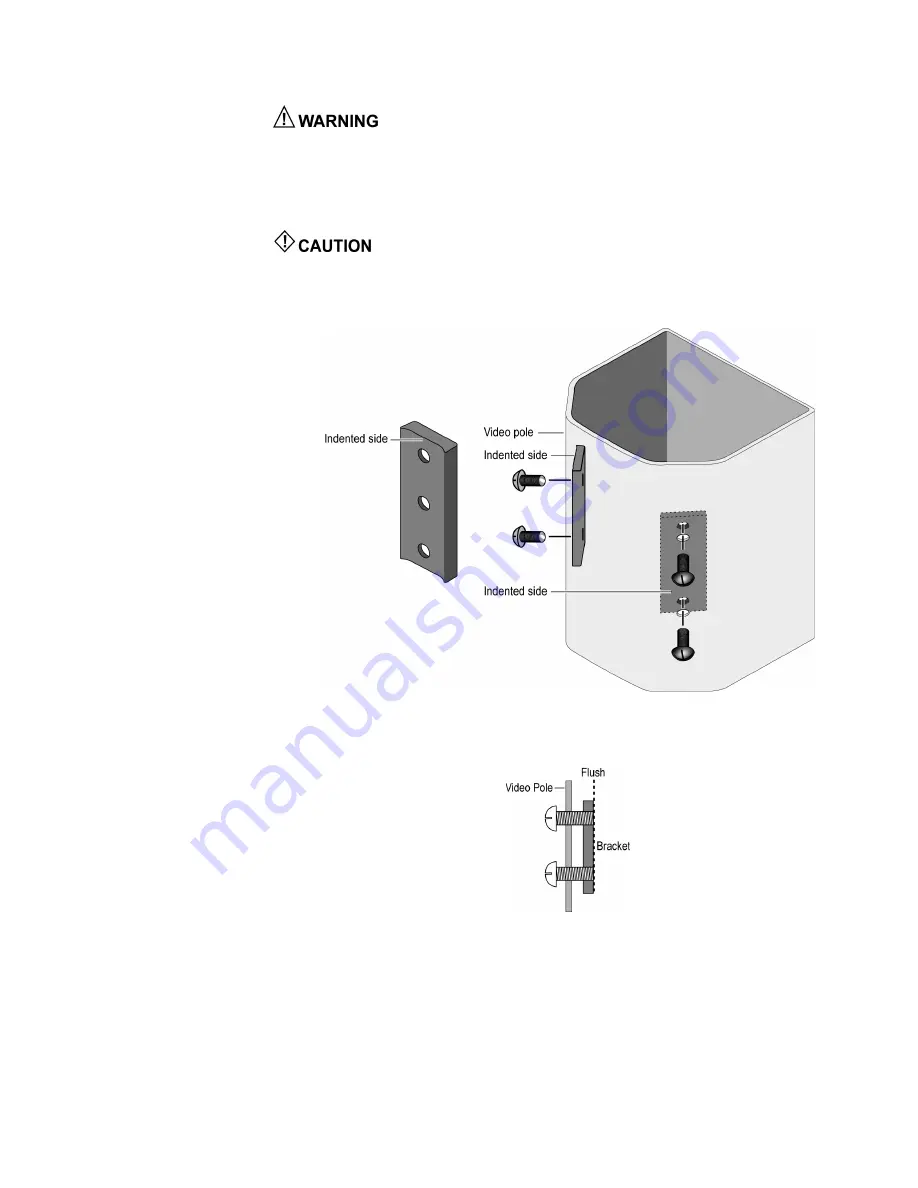
Improper positioning of the two mounting brackets will allow the Video Pole 

to separate from the bottom mast, which may damage system components or cause an injury.

1. Place one of the brackets inside the video pole with the indented side positioned against the 

video pole as shown in Figure 1.

  Figure 1: Proper orientation of the mounting brackets inside the Video Pole.

2. Feed two screws through the Video Pole mounting holes and thread them into the bracket until 

the ends of both screws are flush with the back side of the bracket (Figure 2).

  Figure 2: Thread both screws until they are flush with the bracket.

3. If necessary, repeat steps 1 and 2 for the second bracket.

Summary of Contents for ErgoJust ICU

Page 1: ...Natus ErgoJust and ErgoJust ICU Cart Installation and Functionality Guide Natus ErgoJust cart Natus ErgoJust ICU cart 019667 Rev 05...

Page 2: ......

Page 3: ...Gort Co Galway Ireland Safety and standards conformity The Natus ErgoJust cart meets the following safety standards set by domestic and international regulatory agencies for Medical Electrical Equipme...

Page 4: ...ErgoJust and ErgoJust ICU Cart Installation and Functionality Guide b August 22 2017 Blank page...

Page 5: ...us ErgoJust and Natus ErgoJust ICU cart 1 10 System components 1 10 Preventive maintenance 1 10 General Use Basic ErgoJust cart system component identification 2 2 Basic ErgoJust ICU cart system compo...

Page 6: ...ower cables routings 3 26 ErgoJust ICU Cart Installation Advice to the installer 4 1 Checks 4 1 Mounting the keyboard 4 2 Removing the video pole 4 3 Removing the video pole mounted with the PTZ or HD...

Page 7: ...PTZ video option power cables connections 4 29 PTZ and HD PTZ video option power cables routings 4 30 Fixed zoom video option signal and control cables connections 4 31 Fixed zoom video option signal...

Page 8: ...ErgoJust and ErgoJust ICU Cart Installation and Functionality Guide 4 August 22 2017 Blank page...

Page 9: ...imulator isolation transformer ISO or uninterruptible power supply UPS and basket s for clinical supplies The ErgoJust ICU cart is ideal for EEG monitoring applications in an Intensive Care Unit ICU I...

Page 10: ...s ErgoJust and Natus ErgoJust ICU cart is an accessory for Natus EEG devices based on the NeuroWorks SleepWorks platform It provides a portable workstation that houses all equipment offered by Natus n...

Page 11: ...round ISO 7010 M002 Consult Operating Instructions ISO 7000 1641 Protective earth European Authorized Representative Alternating current Manufacturer On only for a part of the equipment Disposal at en...

Page 12: ...Connecting other medical equipment such as a cardiac pacemaker or other electrical stimulators simultaneously to the same patient may constitute a safety hazard The Natus ErgoJust system is not defibr...

Page 13: ...f Adjust the lift tension so that the monitor and work surface remains stationary Tipping Hazard Failure to comply with the following warnings may result in cart instability leading to equipment damag...

Page 14: ...PS requirements The Natus ErgoJust and Natus ErgoJust ICU cart must be used with a Natus approved ISO or UPS to provide electrically isolated power to all system devices Please contact Natus Technical...

Page 15: ...number EEG Sleep Acquisition Desktop 220V Small form factor only 105075XL 24 FP Monitor or equivalent monitor that meets size and weight requirements PK1102 LED Photic Stimulator 110V EXP1102 LED Pho...

Page 16: ...goJust ICU Cart Audio Pack 019902 ErgoJust ICU Cart Video Extension 005405 EMU40EX Brain Monitor Quantum Headbox Side Quick Disconnect Kit 005406 EMU40EX Brain Monitor Quantum Wall Pole Side Quick Dis...

Page 17: ...ypically within the local government office Natus ErgoJust cart weight capacities Figure 1 shows the maximum weight limitations for the monitor holder work surface and keyboard tray Figure 1 ErgoJust...

Page 18: ...e instrument Be especially careful around controls connectors and edge panels Do not use abrasive cleaners Preventive maintenance Electrical safety testing is recommended It is recommended a schedule...

Page 19: ...August 22 2017 2 1 Chapter 2 General Use This chapter shows how to adjust the various components on the Natus ErgoJust and Natus ErgoJust ICU carts...

Page 20: ...017 Basic ErgoJust cart system component identification Keyboard Mouse Natus Photic Stimulator option Video Camera IR Light and Microphone Amplifier Base Unit ISO or UPS Computer Natus Photic Stimulat...

Page 21: ...3 Basic ErgoJust ICU cart system component identification Keyboard Mouse ISO or UPS Amplifier Base Unit PTZ or HD PTZ Video Camera RJ45 to USB Converter IR Light and Power Supply Fixed Zoom Video Cam...

Page 22: ...caster wheel locking lever is colored blue and has three positions The Up position allows the wheel to roll but does not allow the wheel to swivel Use this position while transporting the cart The Ce...

Page 23: ...ush slowly downward to lower the work surface Figure 2 Adjusting the work surface height Extending the keyboard tray ErgoJust cart only 1 Place your hands below the keyboard tray and lift slowly upwar...

Page 24: ...goJust cart NOTE Store the mouse in the mouse holder when not in use or transporting the cart NOTE The ErgoJust ICU cart system uses the keyboard with an integrated touchpad mouse A separate mouse is...

Page 25: ...ing the cart Raising lowering the monitor or All in One computer The ErgoJust cart uses a small form factor desktop computer and a monitor The ErgoJust ICU cart features a touchscreen All in One AiO c...

Page 26: ...ile in the sitting or standing position Figure 2 Simply rotate or tilt the monitor using both hands to desired position and leave it in place Transporting the ErgoJustandErgoJust ICU cart Do not push...

Page 27: ...uld ensure All cables are routed neatly and secured using the cable management facilities provided The system is connected to a suitable wall socket outlet with a proven protective earth connection Th...

Page 28: ...s ErgoJust cart is equipped with a height limiter on the mast below the Keyboard tray Figure 2 This height limiter is designed to guard against the Keyboard tray from coming in contact with the equipm...

Page 29: ...emove the optional Natus Photic Stimulator 1 Lock the swivel arm in the folded position Figure 1 2 Wrap the Velcro strip around the swivel arm 3 Loosen the swivel arm securing knob 4 Carefully lift an...

Page 30: ...de of the plate pointing outward away from the bottom mast when remounting the video pole Figure 3 Figure 3 Proper mounting plates orientation 7 Loosen the four video pole mounting screws sufficiently...

Page 31: ...the Video Pole to separate from the bottom mast which may damage system components or cause an injury 1 Place one of the brackets inside the video pole with the indented side positioned against the v...

Page 32: ...ing the next step This is necessary to position both brackets properly in order to slide the brackets into both grooves on the bottom mast Figure 3 Press in all four screws tight to the Video Pole 4 W...

Page 33: ...ounting screws Figure 6 Figure 6 Insert and tighten all four Video Pole mounting screws 6 Tighten all four screws until they are firm against the Video Pole Figure 7 Figure 7 Tighten all four video po...

Page 34: ...m allen wrench Figure 1 Figure 1 Mounting the computer 1 Loosen the six securing knobs Figure 1 NOTE There are two securing knobs on the other side of the computer cage which are not shown in Figure 1...

Page 35: ...slide the ISO or UPS into the cage Figure 1 Figure 1 2 Verify Bracket 1 is positioned properly in Slot 1 Figure 2 Figure 2 3 Lower the ISO or UPS and cage such that Tab A inserts into Slot 7 Figure 3...

Page 36: ...ble bundle from the ISO or UPS though the cage s cable cutout Ensure that the tab on the cage inserts into Slot B after tilting the ISO or UPS fully upright Figure 4 Figure 4 6 Feed the Natus Photic S...

Page 37: ...he cage rear cover into the ISO or UPS main cage Figure 7 Figure 7 Slide ISO or UPS cage rear cover into place 9 Secure the rear cover to the ISO or UPS main cage using three screws Figure 8 Figure 8...

Page 38: ...ic Stimulator option swivel arm Mounting the Natus Amplifier Base Unit NOTE Ensure the Amplifier Base Unit has a Headbox Side Quick Disconnect Bracket attached 1 Insert the four mounting pins on the r...

Page 39: ...l cover aside Figure 1 Removing the cable channel cover With an assistant hold on to the IR Light and Microphone during the next step to guard against dropping the IR Light and Microphone 2 Using an a...

Page 40: ...amera during the next step to guard against dropping the camera 1 Install and tighten the four Video Camera mounting screws Figure 1 Figure 1 Mounting the Video Camera Mounting the display monitor 1 W...

Page 41: ...e handle Figure 2 until the basket mounting tab is free from the side mounting hole Figure 2 Carefully pry the side of the basket away from the handle and pull basket down 3 Carefully pull downward on...

Page 42: ...A slightly away from the handle and swing the bottom of the basket B towards yourself until the two basket mounting tabs snap free from the two mounting holes Figure 2 Figure 2 Removing the basket fro...

Page 43: ...ng plates and set the damaged handle aside IMPORTANT Ensure the two mounting plates are orientated properly as shown in Figure b before starting the next step Figure b Proper mounting plates orientati...

Page 44: ...e of the basket upward 6 Press in on the left side of the basket or carefully pry the left side of the basket while pushing up on the bottom of the basket until the mounting tab slides into the mounti...

Page 45: ...injury 8 Place one of the brackets inside the video pole with the indented side positioned against the video pole as shown in Figure 7 Figure 7 Proper orientation of the mounting brackets inside the V...

Page 46: ...to the Video Pole 12 With an assistant carefully lower the Video Pole onto the bottom mast ensuring that both brackets slide inside the two slots Figure 10 Figure 10 Proper placement of the mounting b...

Page 47: ...roper input voltage Make sure all voltage settings for each component of your system are set properly for the voltage source you will be using Verify fuse amperage matches in input voltage rating on t...

Page 48: ...r the ISO or UPS Figure 3 Figure 3 Removing the cable channel cover The Video Camera IR Light and Microphone cables feed through the video pole which may require removing the cable channel cover to ac...

Page 49: ...ErgoJust Cart System August 22 2017 3 23 Signal and control cables connections See the cable routing diagram on the next page Figure 1 Cabling the system components...

Page 50: ...ErgoJust and ErgoJust ICU Cart Installation and Functionality Guide 3 24 August 22 2017 Signal and control cables routings Figure 1 Signal and control cable routings...

Page 51: ...ns Ensure that the ISO or UPS is disconnected unplugged from the MAINS power source before connecting power cables to the system components NOTE ISO is shown in the example below See the cable routing...

Page 52: ...ErgoJust and ErgoJust ICU Cart Installation and Functionality Guide 3 26 August 22 2017 System power cables routings Figure 1 Power cable routings...

Page 53: ...er should ensure All cables are routed neatly and secured using the cable management facilities provided The system is connected to a suitable wall socket outlet with a proven protective earth connect...

Page 54: ...n firmly to secure the keyboard to the tray Figure 1 Keyboard location NOTE The Natus ErgoJust cart is equipped with a height limiter on the mast below the Keyboard tray Figure 2 This height limiter i...

Page 55: ...oving the video pole mounted with the PTZ or HD PTZ video camera 1 Unplug the video camera cable Figure 1 2 Unplug the video camera and IR light power cables Figure 1 Unplug video camera cable and vid...

Page 56: ...le mounting screws sufficiently to allow the video pole to be lifted away from the bottom mast Figure 3 4 Using an assistant carefully lift the video pole away from the bottom mast and set it aside Fi...

Page 57: ...ed zoom video camera 1 Cut and remove the tie wraps shown below Figure 1 Figure 1 Remove the tie wraps 2 Unplug the video camera cable Figure 2 3 Unplug the video camera and camera control cables Figu...

Page 58: ...l Figure 3 Unplug the video power supply and remove the video power cable from the channel IMPORTANT Do NOT remove the mounting screws during the following step If the mounting screws are removed the...

Page 59: ...ficiently to allow the video pole to be lifted away from the bottom mast Figure 5 7 Using an assistant carefully raise the video pole away from the bottom mast and set it aside Figure 6 Figure 5 Loose...

Page 60: ...two mounting brackets will allow the Video Pole to separate from the bottom mast which may damage system components or cause an injury 1 Place one of the brackets inside the video pole with the indent...

Page 61: ...s is necessary to position both brackets properly in order to slide the brackets into both grooves on the bottom mast Figure 3 Press in all four screws tight to the Video Pole 4 With an assistant care...

Page 62: ...Remove the Video Pole and repeat step 4 above 5 Tighten all four screws until they are firm against the Video Pole Figure 6 Figure 6 Tighten all four video pole mounting screws 6 Wiggle the Video Pol...

Page 63: ...nd slide the ISO or UPS into the cage Figure 1 Figure 1 2 Verify Bracket 1 is positioned properly in Slot 1 Figure 2 Figure 2 3 Lower the ISO or UPS and cage such that Tab A inserts into Slot 7 Figure...

Page 64: ...ble bundle from the ISO or UPS though the cage s cable cutout Ensure that the tab on the cage inserts into Slot B after tilting the ISO or UPS fully upright Figure 4 Figure 4 6 Feed the Natus Photic S...

Page 65: ...the cage rear cover into the ISO or UPS main cage Figure 7 Figure 7 Slide ISO or UPS cage rear cover into place 9 Secure the rear cover to the ISO or UPS main cage using three screws Figure 8 Figure...

Page 66: ...quick disconnect bracket Figure 1 and slide the Amplifier Base Unit downward until the locking pin snaps into the quick disconnect bracket locking hole 2 To remove the Base Unit pull the locking pin o...

Page 67: ...and IR light with microphone Figure 1 Figure 1 PTZ HD PTZ video camera and IR light with microphone Mounting the video camera With an assistant hold on to the video camera during the next step to gua...

Page 68: ...and set the cable channel cover aside Figure 1 Removing the cable channel cover With an assistant hold on to the IR Light and Microphone during the next step to guard against dropping the IR Light and...

Page 69: ...microphone Mounting the microphone option 1 Unscrew the cable channel mounting knob Figure 2 and set the cable channel cover aside Figure 2 Removing the cable channel cover 2 Mount the microphone brac...

Page 70: ...nt to the video camera Figure 3 With an assistant hold on to the video camera during the next step to guard against dropping the camera 2 Attach the video camera mount to the video camera bracket Figu...

Page 71: ...the handle Figure 2 until the basket mounting tab is free from the side mounting hole Figure 2 Carefully pry the side of the basket away from the handle and pull basket down 3 Carefully pull downward...

Page 72: ...A slightly away from the handle and swing the bottom of the basket B towards yourself until both basket mounting tabs snap free from the two mounting holes Figure 2 Figure 2 Removing the basket from...

Page 73: ...ting plates and set the damaged handle aside IMPORTANT Ensure the two mounting plates are orientated properly as shown in Figure b before starting the next step Figure b Proper mounting plates orienta...

Page 74: ...of the basket upward 6 Press in on the left side of the basket or carefully pry the left side of the basket while pushing up on the bottom of the basket until the mounting tab slides into the mountin...

Page 75: ...n injury 8 Place one of the brackets inside the video pole with the indented side positioned against the video pole as shown in Figure 7 Figure 7 Proper orientation of the mounting brackets inside the...

Page 76: ...to the Video Pole 12 With an assistant carefully lower the Video Pole onto the bottom mast ensuring that both brackets slide inside the two slots Figure 10 Figure 10 Proper placement of the mounting b...

Page 77: ...our system are set properly for the voltage source you will be using Verify fuse amperage matches in input voltage rating on the label Make sure the ISO or UPS Power switch is in the OFF position and...

Page 78: ...o Camera IR Light and Microphone cables feed through the video pole which may require removing the cable channel cover to access the cables 1 Unscrew the cable channel mounting knob Figure 1 and set t...

Page 79: ...017 4 27 PTZ and HD PTZ video option signal and control cables connections See the PTZ and HD PTZ video option signal and control cable routing diagram on the next page Figure 1 PTZ and HD PTZ option...

Page 80: ...and ErgoJust ICU Cart Installation and Functionality Guide 4 28 August 22 2017 PTZ and HD PTZ option signal and control cables routings Figure 1 PTZ and HD PTZ video option signal and control cable r...

Page 81: ...nnections Ensure that the ISO or UPS is disconnected unplugged from the MAINS power source before connecting power cables to the system components See the PTZ and HD PTZ video option power cable routi...

Page 82: ...ErgoJust and ErgoJust ICU Cart Installation and Functionality Guide 4 30 August 22 2017 PTZ and HD PTZ video option power cables routings Figure 1 PTZ and HD PTZ video option power cable routings...

Page 83: ...August 22 2017 4 31 Fixed zoom video option signal and control cables connections See the Fixed zoom video option cable routing diagram on the next page Figure 1 Fixed zoom video option signal and co...

Page 84: ...t and ErgoJust ICU Cart Installation and Functionality Guide 4 32 August 22 2017 Fixed zoom video option signal and control cables routings Figure 1 Fixed zoom video option signal and control cable ro...

Page 85: ...System August 22 2017 4 33 Securing the cables with tie wraps 1 Attach tie wraps to the ErgoJust ICU cart cables as shown below after cabling the system components Figure 1 Figure 1 Securing the cabl...

Page 86: ...deo option power cables connections Ensure that the ISO or UPS is disconnected unplugged from the MAINS power source before connecting power cables to the system components See the Fixed zoom video op...

Page 87: ...ErgoJust ICU Cart System August 22 2017 4 35 Fixed zoom video option power cables routings Figure 1 Fixed zoom video option power cable routings...

Page 88: ...ErgoJust and ErgoJust ICU Cart Installation and Functionality Guide 4 36 August 22 2017 Blank page...

Page 89: ...e 3 16 Replacing a damaged handle 3 17 Verifying the ISO or UPS voltage 3 21 ErgoJust cart system component identification 2 2 ErgoJust Cart System Installation Extending the work tray 3 2 Replacing a...

Page 90: ...Representative a P Patient isolation requirements 1 6 Preventive maintenance 1 10 PTZ video camera 1 1 Publisher s notice a S Safety and standards conformity a Safety summary 1 4 Symbol convention des...

Page 91: ......

Page 92: ...ia WebEx or VPN the largest clinical and technical field support network in Neuro Sleep and cus tomized service contracts that include preventative maintenance visits and computer upgrades Natus Medic...

Reviews: