


Chapter 3
Connecting the UMI-7774/7772 to Drives and Other Devices
National Instruments UMI-7774/7772 User Manual
3-16
ni.com
Feedback Connector for Each Axis
Each axis connected to the UMI-7774/7772 has a 25-pin D-SUB feedback
connector to which you can wire incremental encoders, limits, and home
sensors. The feedback connectors for axes 1 and 2 have additional
connections for Hall effect sensors for brushless motors. Figure 3-5 shows
the pin locations of the feedback connector for each axis. Table 3-5 shows
the corresponding signals for each pin.
Note
The Hall sensors are available only on Feedback connectors 1 and 2.
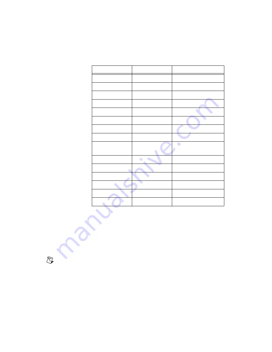
Table 3-4.
Control 2 Connector Pin Assignment for Sinusoidal Commutation
Pin
Signal
Optically Isolated
1
Analog Output 2
No
2
Analog Output 4
No
3
+5 V (Output)
No
4
Step (CW)
No
5
NC
No
6
Enable Output
Yes
7
Fault +
Yes
8
Iso Power (Output)
Yes
9
Analog Output
Ground
No
10
Digital Ground
No
11
Digital Ground
No
12
Dir (CCW)
No
13
NC
No
14
Fault –
Yes
15
Iso Common
Yes


