background image

NI 1357/1358/1359 Kit Installation Guide

8

ni.com

3.

Select 

NI-DAQmx SCXI Chassis

, and choose the chassis. 

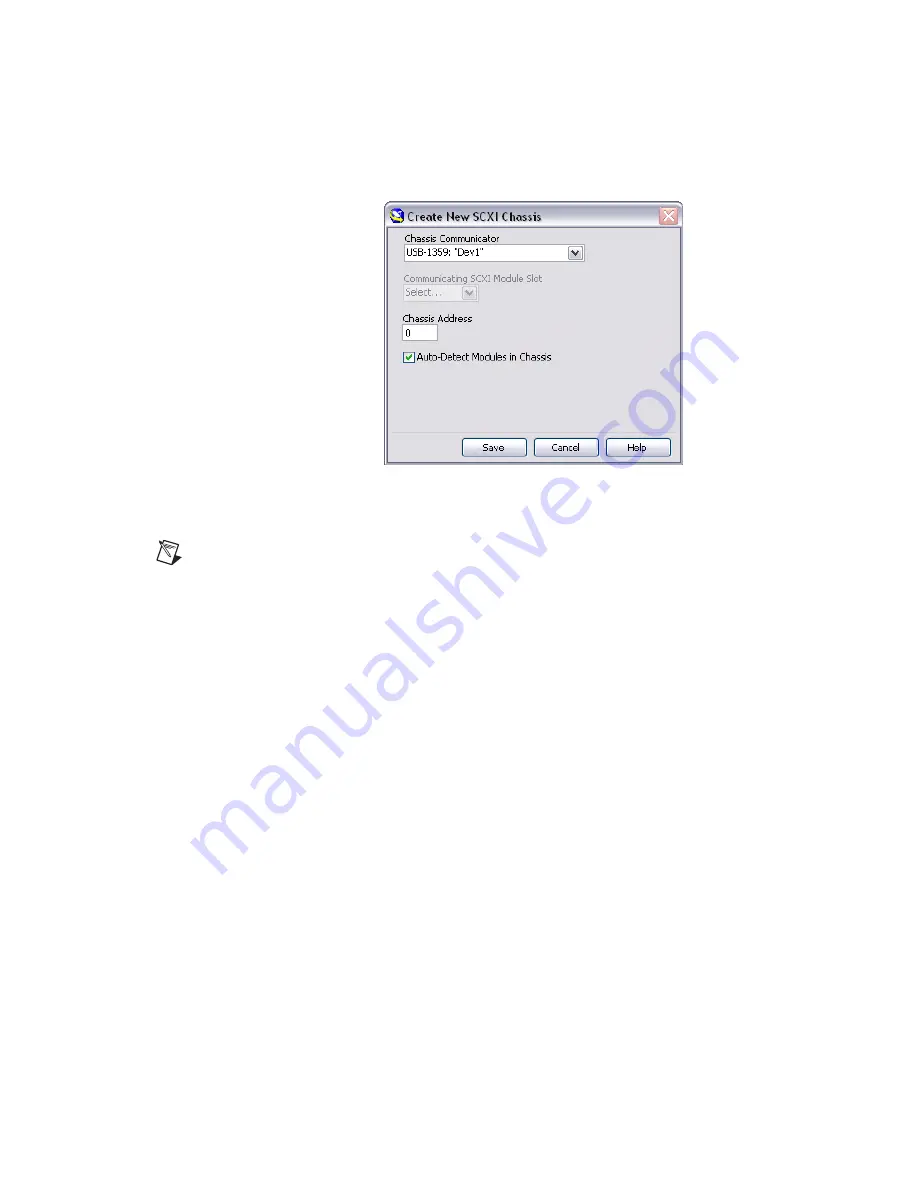
The Create New SCXI Chassis dialog box opens as shown in Figure 7.

Figure 7.  

Configuring the Create New SCXI Dialog Box

4.

Create a new SCXI chassis:

Note

If you are using an NI PXI-1010 chassis and the switch controller is 

not

 in the 

rightmost PXI slot, create the chassis as an NI SCXI-1000 in MAX.

a.

Select the switch controller (NI USB-1359 or 
NI 4021/4060/407

x

) cabled to the communicating SCXI switch 

module from the 

Chassis Communicator 

listbox. If MAX 

detects only one communicating device, this device is selected as 
the chassis communicator by default and the listbox is dimmed.

b.

SCXI kits only—Select the module slot connected to the chassis 
communicator from the 

Communicating SCXI Module Slot


listbox.

c.

Enter the chassis address setting in the 

Chassis Address 

field. 

Ensure that the setting you enter matches the address setting on 
the SCXI chassis as shown in Figure 6.

d.

Enable the auto-detect option to auto-detect installed SCXI switch 
modules. If you do not auto-detect switch modules, MAX disables 
the Communicating SCXI Module Slot listbox.

e.

Click 

Save

.

After creating a new chassis, the SCXI Chassis Configuration dialog 
box opens as shown in Figure 8. The 

Modules 

tab is selected by 

default.

Summary of Contents for SCXI USB-1357

Page 1: ...USB 1357...

Page 2: ...ge signals among switches Introduction Note Both SCXI and USB kits connect to an SCXI switch with a 10 pin rear connector Refer to the NI Switches Getting Started Guide to determine the switches and s...

Page 3: ...I DAQ 7 4 or later before you install the NI 1357 1358 1359 kit Complete the following steps to install the NI 1357 1358 1359 kit 1 Power off and unplug the SCXI chassis Follow proper electrostatic di...

Page 4: ...the switch controller Refer to Figures 2 and 3 to verify the connector positions on the NI 1359 Figure 2 2 Slot HVAB Backplane Adapter Connectors Figure 3 8 Slot HVAB Backplane Adapter Connectors 1 HV...

Page 5: ...ts Connect one end of the SH9MD AUX cable to the NI SCXI 1359 cable adapter and the other end to the NI 4021 4060 407x switch controller as shown in Figure 4 Figure 4 Cabling an NI 4021 4060 407x Swit...

Page 6: ...configure the switch module Multichassis Configuration Complete the following steps to create a multichassis switch configuration 1 Complete the Installing the Kit section steps 1 through 7 for each c...

Page 7: ...of the HVAB backplane adapter and the other end to the NI 4021 4060 407x switch controller b Using another SH9MD AUX cable connect the AUX OUT of the HVAB backplane adapter on the first chassis to th...

Page 8: ...ure SCXI switch modules cabled to an NI SCXI 1357 1358 1359 kit proceed directly to step 4 to create a new SCXI chassis If you are using NI DAQmx to configure SCXI switch modules cabled to an NI USB 1...

Page 9: ...MAX detects only one communicating device this device is selected as the chassis communicator by default and the listbox is dimmed b SCXI kits only Select the module slot connected to the chassis com...

Page 10: ...it the default name click the Device Identifier textbox and enter a unique alphanumeric ID for the switch module c If you are using a connected accessory such as a terminal block select it from the Ac...

Page 11: ...witch module information A message at the top of the SCXI Chassis Configuration dialog box displays the configuration status If a warning appears in the message box you can save the configuration If a...

Page 12: ...NI SCXI 1129 150 V CAT I Example 2 NI SCXI 1000 chassis NI SCXI 1359 2 slot backplane adapter behind Slots 3 and 4 NI SCXI 1127 300 V CAT II in Slot 4 NI SCXI 1129 150 V CAT I in Slot 2 The NI SCXI 11...

Page 13: ...1 UL 61010 1 CAN CSA C22 2 No 61010 1 Note For UL and other safety certifications refer to the product label or visit ni com certification search by model number or product line and click the appropr...

Reviews: