


Chapter 2
Connecting the Signals
©
National Instruments Corporation
2-9
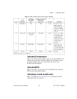
Connecting Thermocouples
Refer to the terminal block installation guide, such as the SCXI-1303, for
information about connecting thermocouples. NI recommends using an
isothermal terminal block, such as the SCXI-1303, for accurate
thermocouple measurements.
Connecting RTDs
Refer to the
SCXI-1581 User Manual
for information about connecting
RTDs and for additional RTD theory.
Connecting a Current-Loop Receiver
Refer to Appendix E,
, for information about
connecting current loop receivers.
29
SLOT0SEL*
P0.2
DIO2
Input
Slot 0 select—this
signal taps into the
SCXIbus INTR* line to
indicate whether the
information on MOSI is
being sent to a module
or Slot 0.
36
SCANCLK
AI HOLD COMP,
AI HOLD
SCANCLK
Input
Scan clock—a rising
edge indicates to the
scanned SCXI module
that the E/M Series
DAQ device has taken a
sample and causes the
module to advance
channels.
37
SER CLK
EXTSTROBE*
EXTSTROBE*
Input
Serial clock—this
signal taps into the
SCXIbus SPICLK line
to clock the data on the
MOSI and MISO lines.
43, 46
RSVD
RSVD
RSVD
Input
Reserved.
Note
: All other pins are not connected.
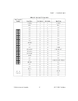
Table 2-4.
SCXI-1102/B/C Communication Signals (Continued)
Pin
SCXI
Signal Name
NI-DAQmx
Device Signal
Name
Traditional NI-DAQ
(Legacy) Device
Signal Name
Direction
Description


