


Chapter 2
Connecting the Signals
©
National Instruments Corporation
2-3
Front Connector Signal Descriptions
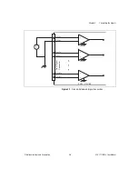
Analog Input Signal Connections
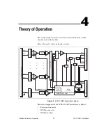
The signal terminals for the negative input channel are located in column B
of the connector. The signal terminal for each corresponding positive input
channel is located in column C of the connector. Each input goes to a
separate filter and amplifier that is multiplexed to the module output buffer.
If the terminal block has a temperature sensor, the sensor output—
connected to pins A3 and A4 (CJ SENSOR)—is also filtered and
multiplexed to the module output buffer.
The differential input signal range of an SCXI-1102/B/C module input
channel is ±10 V when using a gain of 1 or ±0.1 V when using a gain of
100. This differential input range is the maximum measurable voltage
difference between the positive and negative channel inputs. The
common-mode input signal range of an SCXI-1102/B/C module input
channel is ±10 V. This common-mode input range for either positive or
negative channel input is the maximum input voltage that results in a valid
measurement. Each channel includes input protection circuitry to withstand
the accidental application of voltages up to ±42 VAC peak or 60 VDC.
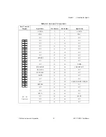
Table 2-2.
Front Connector Signals
Pin
Signal Name
Description
A1
+5 V
+5 VDC Source—Used to power the
temperature sensor on the terminal block.
0.2 mA of source not protected.
A2, A5, A16, A24,
A32
CH GND
Chassis Ground—Tied to the SCXI chassis.
A3, A4
CJ SENSOR
Cold-junction Temperature Sensor
Input—Connects to the temperature sensor
of the terminal block.
B1–B32
AI 31 – through AI 0 –
Negative Input Channels—Negative side of
differential input channels.
C1–C32
AI 31 + through AI 0 +
Positive Input Channels 31 through
0—Positive side of differential input
channels.
Note
: All other pins are not connected.


