


Chapter 5
Programming
5-14
www.natinst.com
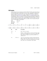
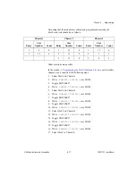
5.
Write binary
101S 1100
to the HSCR.
6.
Write binary
101S 1110
to the HSCR.
7.
Write binary
101S 1111
to the HSCR.
In the preceding steps, S = 0 if you want the scanning to repeat when the
end of the list is reached. S = 1 if you want the circuitry to shut down after
a single scan.
When you are writing multiple entries to the same register, for example,
repetitive writes to the HSCR or several FIFO entries, it is important that
SS*13 or SS*14 go inactive (high) between each entry. Select another slot
or toggle the SLOT0SEL* line to temporarily deassert the appropriate SS*
line.
If consecutive scan list entries access an SCXI-1121, the module will reload
the MUXCOUNTER with the starting channel after each entry. Thus, two
entries with counts of two for one module will yield different behavior than
one entry with a count of four.
For multiple-chassis scanning, program each Slot 0 with dummy entries to
fill the sample counts when the data acquisition board is accessing other
chassis. Use Slot 13 as the dummy entry slot.
See
at the end of this chapter.
4. Acquisition Enable, Triggering, and Servicing
At this point, you should now continue from where you left off in the
1. Data Acquisition Board Setup Programming
section of this chapter.
Perform the following steps given in your data acquisition board user
manual.
•
MIO Board User Manual
–
Enable the scanning data acquisition operation.
–
Apply a trigger.
–
Service the data acquisition operation.
•
Lab-PC User Manual, Lab-PC+ User Manual, and PC-LPM-16 User
Manual
–
Start and service the data acquisition operation.
•
Lab-LC User Manual
–
Program the sample-interval counter.
–
Service the data acquisition operation.


