


© National Instruments
|
2-9
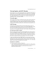
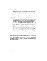
Figure 2-9.
NI PXIe-4302/4303 Block Diagram
Signal Acquisition Considerations
This section contains information about signal acquisition concepts, including operation modes,
Delta-Sigma converters, Nyquist frequency and bandwidth, timing, triggering, and
synchronization.
Nyquist Frequency and Nyquist Bandwidth
Any sampling system, such as an ADC, is limited in the bandwidth of the signals it can measure.
Specifically, a sampling rate of
f
s
can represent only signals with frequencies lower than
f
s
/2.
This maximum frequency is known as the
Nyquist frequency
. The bandwidth from 0 Hz to the
Nyquist frequency is the
Nyquist bandwidth
.
ADC
The NI PXIe-4302/4303 ADCs use a conversion method known as delta-sigma modulation. This
approach involves oversampling the input signal and then decimating and filtering the resulting
data to achieve the desired sample rate. The NI PXIe-4302 supports rates of 1 S/s to 5 kS/s. The
NI PXIe-4303 supports rates of 1 S/s to 51.2 kS/s.
Operation Modes
The NI PXIe-4302/4303 supports two modes of operation: Buffered Mode and Hardware-Timed
Single Point Mode. In a Buffered Mode acquisition, oversampled data is decimated to your
requested sample rate and digital anti-alias filters are applied to filter out frequency content
above the Nyquist frequency. These digital anti-alias filters introduce group delay and for some
applications this may be undesirable. For this reason, the NI PXIe-4302/4303 also supports
Ch
a
nnel 0
Ch
a
nnel 1
Ch
a
nnel 7
Ch
a
nnel 0 to Ch
a
nnel 7
Ch
a
nnel 8 to Ch
a
nnel 15
Ch
a
nnel 24 to Ch
a
nnel
3
1
Ch
a
nnel 16 to Ch
a
nnel 2
3
I/O
Connector
AIGND
GND
AI0+
AI0–
AI1+
AI1–
AI7+
AI7–
D
S
P
S
tre
a
ming, Digit
a
l Filter
& PXIe B
us
Interf
a
ce
PXIe B
us
G
a
in
(1 or 100)
An
a
log
Anti-Ali
as
Filter
ADC
Protection


