


1.
Power off the computer or chassis that contains the device.
2.
Reinstall the device and make any necessary adjustments to make sure that the device is
effectively cooled.
3.
Power on the computer or chassis.
Note
The thermal shutdown error is reported until the device has cooled to an
acceptable operating temperature and has been successfully reset.
For more information about cooling the device, refer to the
Maintain Forced-Air Cooling
Note to Users
included in your kit.
Related Information
on page 5
on page 6
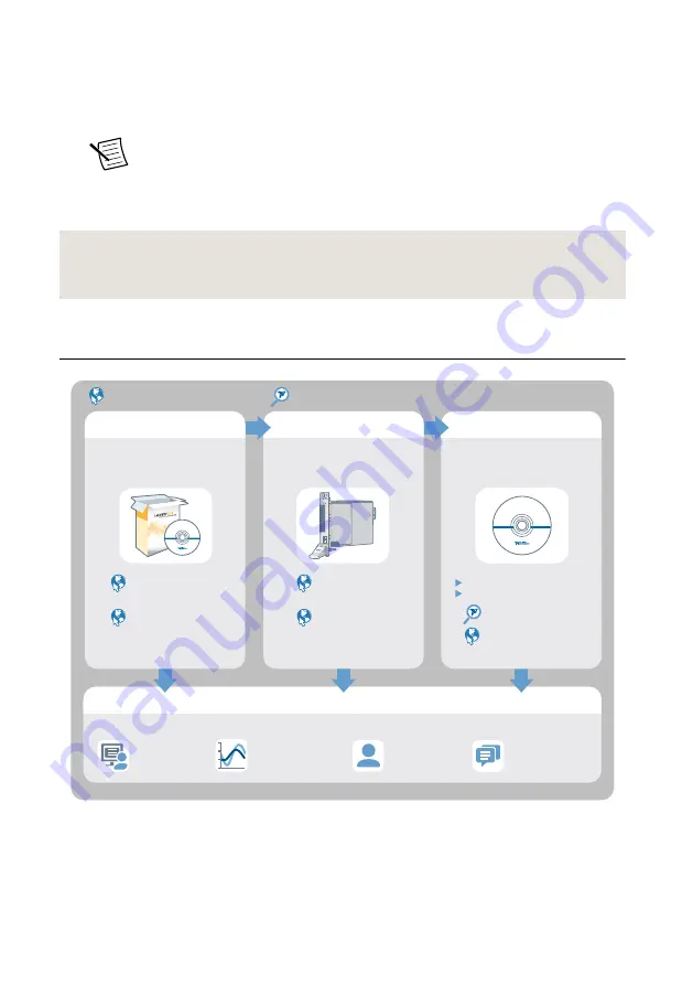
Where to Go Next
NI PXIe-4112
EXPLORE
LEARN
CREATE
DISCOVER
Located online at ni.com/manuals
the application development
environment (ADE)
for your application.
about hardware features
or review device
specifications.
custom applications with
an application programming
interface (API).
NI PXI/PCI-5154
Specifications
NI High-Speed
Digitizers Help
NI-SCOPE Soft Front Panel
NI-SCOPE Instrument Driver
NI High-Speed
Digitizers Help
NI-SCOPE Examples
Located using the NI Example Finder
Services
ni.com/services
NI Community
ni.com/community
Support
ni.com/support
more about your products through ni.com.
NI Oscilloscopes
ni.com/oscilloscope
Getting Started with
LabWindows/CVI
Getting Started with
LabVIEW
PXI/PCI-5154 Getting Started Guide
|
© National Instruments
|
15


