Chapter 3
Signal Connections
3-14
ni.com
Counter Pairs
Each co
u
nter on the TIO is paired with another co
u
nter. This pairing allows
some co
u
nter signals to connect to signals on the other co
u
nter. The
co
u
nters are paired as ctr0 with ctr1, ctr2 with ctr 3, ctr 4 with ctr5, and ctr6
with ctr7.
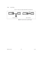
Ctr0InternalO
u
tp
u
t, which yo
u
can connect to Ctr1Gate, is an example of
two signals that yo
u
can connect between the ctr0/ctr1 pair. Conversely, to
connect Ctr0InternalO
u
tp
u
t to Ctr2Gate, yo
u
m
u
st
u
se other circ
u
itry on
the TIO device (s
u
ch as RTSI Triggers).
Note
The NI 6601
u
ses co
u
nters <0..3> only.
Counter Applications
Yo
u
can
u
se the TIO device in the following co
u
nter-based applications:
•
Co
u
nting Edges
•
Freq
u
ency Meas
u
rement
•
Period Meas
u
rement
•
Position Meas
u
rement with Linear and Ang
u
lar Encoders
•
P
u
lse Width Meas
u
rement
•
Semi-Period Meas
u
rement
•
Two-Edge Separation Meas
u
rement
•
P
u
lse Generation
Yo
u
can perform these meas
u
rements thro
u
gh programmed I/O, interr
u
pt,
or DMA data transfer mechanisms. The meas
u
rements can be finite or
contin
u
o
u
s in d
u
ration. Some of the applications also
u
se start triggers,
pa
u
se triggers, and hardware arm triggers.
Note
For more information abo
u
t programming co
u
nter applications and triggers in
software, refer to the
NI-DAQmx Help
, and/or
u
se the examples that are available with
NI-DAQmx.
Real-Time System Integration Bus
TIO devices
u
se the National Instr
u
ments Real-Time System Integration
(RTSI) b
u
s to easily synchronize several meas
u
rement f
u
nctions to a
common trigger or timing event. In a PCI system, the RTSI b
u
s consists of
the RTSI b
u
s interface and a ribbon cable. The b
u
s can ro
u
te timing and
Summary of Contents for PCI-6601
Page 1: ...PCI 6601...

