background image

Chapter 1

Introduction

©

 National Instruments Corporation

1-3

NI PCI-5911 User Manual

Figure 1-2.  

9-Pin Mini-Circular DIN Connector

Acquiring Data with the NI 5911

You can acquire data either programmatically—by writing an application 
for the NI 5911—or interactively with the Scope Soft Front Panel.

Programmatically Controlling the NI 5911

To help you get started programming the NI 5911, NI-SCOPE includes 
examples that you can use or modify. 

You can find examples for the following ADEs in these locations:

LabVIEW—Go to 

Program Files\National Instruments\

LabVIEW\Examples\Instr\niScopeExamples\

LabWindows

/CVI

, C, and Visual Basic with 

Windows 2000/NT—Go to 

vxipnp\winnt\Niscope\Examples\

.

LabWindows/CVI, C, and Visual Basic with Windows 98/95—Go to 

vxipnp\win95\Niscope\Examples\c\

.

For information on using NI-SCOPE to programmatically control your 
digitizer, refer to the 

NI-SCOPE Software User Manual

. Another resource 

is the 

NI-SCOPE Instrument Driver Quick Reference Guide

, which 

contains abbreviated information on the most commonly used functions 
and LabVIEW VIs. For more detailed function reference help, refer to the 

1

+5 V (Fused)

2

GND

3

Reserved

4

Reserved

5

Reserved

6

PFI  2

7

Reserved

8

Reserved

9

Reserved

4

3

5

6

7

8

9

1

2

Summary of Contents for PCI-5911

Page 1: ...Modular Instrumentation NI PCI 5911 User Manual High Speed Digitizer with Flex ADC NI PCI 5911 User Manual March 2003 Edition Part Number 322150E 01...

Page 2: ...ermany 49 0 89 741 31 30 Greece 30 2 10 42 96 427 India 91 80 51190000 Israel 972 0 3 6393737 Italy 39 02 413091 Japan 81 3 5472 2970 Korea 82 02 3451 3400 Malaysia 603 9131 0918 Mexico 001 800 010 07...

Page 3: ...ion or maintenance instructions owner s modification of the product owner s abuse misuse or negligent acts and power failure or surges fire flood accident actions of third parties or other events outs...

Page 4: ...Rules Class A Federal Communications Commission This equipment has been tested and found to comply with the limits for a Class A digital device pursuant to part 15 of the FCC Rules These limits are d...

Page 5: ...w Differential Programmable Gain Input Amplifier PGIA 2 1 Differential Input 2 1 Grounding Considerations 2 2 Input Ranges 2 3 Input Impedance 2 3 Input Bias 2 4 Input Protection 2 4 AC Coupling 2 4 C...

Page 6: ...and Memory Usage 2 10 Multi Record Acquisitions 2 11 RTSI Bus and Clock PFI 2 11 PFI Lines 2 11 PFI Lines as Inputs 2 12 PFI Lines as Outputs 2 12 Synchronization 2 12 Appendix A Specifications Appen...

Page 7: ...item and select Options from the last dialog box This icon denotes a note which alerts you to important information This icon denotes a caution which advises you of precautions to take to avoid injury...

Page 8: ...ice only with the chassis devices accessories and cables specified in the installation instructions You must have all covers and filler panels installed during operation of the device Do not operate t...

Page 9: ...m referred to as MAINS3 voltage This category is for measurements of voltages from specially protected secondary circuits Such voltage measurements include signal levels special equipment limited ener...

Page 10: ...onary motors with permanent connections to fixed installations Installation Category IV is for measurements performed at the primary electrical supply installation 1 000 V Examples include electricity...

Page 11: ...the NI 5911 refer to the Where to Start with Your NI Digitizer document For multiple device considerations refer to the Operating Environment section of Appendix A Specifications Connecting Signals Fi...

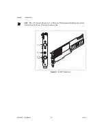
Page 12: ...on NI PCI 5911 User Manual 1 2 ni com Note The 5 V signal is fused at 1 1 A However NI recommends limiting the current from this pin to 30 mA The fuse is self resetting Figure 1 1 NI 5911 Connectors C...

Page 13: ...Go to Program Files National Instruments LabVIEW Examples Instr niScopeExamples LabWindows CVI C and Visual Basic with Windows 2000 NT Go to vxipnp winnt Niscope Examples LabWindows CVI C and Visual...

Page 14: ...teractively Controlling the NI 5911 with the Scope Soft Front Panel The Scope Soft Front Panel allows you to interactively control the NI 5911 as you would a desktop oscilloscope To launch the Scope S...

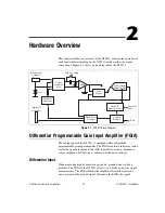
Page 15: ...rately interfaces to and scales the signal presented to the ADC regardless of source impedance source amplitude DC biasing or common mode noise voltages Differential Input When measuring high dynamic...

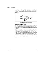
Page 16: ...versing the inputs results in higher distortion and lower bandwidth The negative input of the amplifier is grounded to PC ground through a 10 k resistor The PGIA is therefore referenced to ground so i...

Page 17: ...cquire an AC coupled or 0 V signal The input stage of the NI 5911 requires a settling time that depends on which vertical range you are switching from and which vertical range you are switching to How...

Page 18: ...rom AC and DC signals up to 42 V If the voltage at one of these inputs exceeds a threshold voltage Vtr the input clamps to Vtr and a resistance of 100 k is inserted in the path to minimize input curre...

Page 19: ...tortion analysis and other measurements for which high resolution is crucial Conventional Mode The ADC converts at a constant rate of 100 MS s but you can choose to store only a fraction of these samp...

Page 20: ...signal data will be invalid In this case you receive an overload warning You must then either select a higher input range or attenuate the signal How Flexible Resolution Works The ADC can be sourced t...

Page 21: ...ction or a LabVIEW VI Refer to Chapter 3 Common Functions and Examples of the NI SCOPE Software User Manual for step by step instructions for self calibrating the NI 5911 When Self Calibration Is Need...

Page 22: ...ccurred may not be obvious from inspecting the data because of the digital filtering that takes place on the acquired data Therefore a warning occurs to notify you that the data includes some samples...

Page 23: ...in increments of 20 V 170 118 mV A hysteresis value may also be associated with the trigger that can be set in the same size increments The hysteresis value creates a trigger window the signal must pa...

Page 24: ...ser Manual Memory The NI 5911 allocates at least 4 kB of onboard memory for each record in a single multi record acquisition Samples are stored in this buffer before transfer to the host computer Thus...

Page 25: ...e digitizer before the data is fetched Therefore the dead time or the time when the digitizer is not ready for a trigger is extremely small For more information on multi record acquisitions and dead t...

Page 26: ...y input through the RTSI bus clock line or a PFI input The NI 5911 can also output its 10 MHz reference on the RTSI bus clock line or a PFI line so that additional NI 5911 devices or other equipment c...

Page 27: ...User Manual route that trigger over the RTSI bus to trigger the other digitizer s However the trigger that is routed to the other digitizer s is sent synchronously to an internal 25 MHz clock For more...

Page 28: ...xible Resolution Mode Number of channels 1 Number of flexible resolution ADC 1 Max RIS sample rate 1 GS s Max real time sample rate 100 MS s Resolution Sample Rate Mode Effective Resolution 100 n MS s...

Page 29: ...0 n MS s Conventional 4 MS 16 MS 12 5 MS s Flexible Resolution 1 MS 4 MS 5 MS s Flexible Resolution 1 MS 4 MS 2 5 MS s Flexible Resolution 1 MS 4 MS 1 MS s Flexible Resolution 1 MS 4 MS 500 kS s Flexi...

Page 30: ...lexible resolution mode Input coupling DC and AC software selectable AC coupling cut off frequency 3 dB 2 5 Hz 0 5 Hz Input impedance 1 M 2 Max measurable input voltage 10 V DC peak AC Input protectio...

Page 31: ...S s Flexible Resolution 400 kHz 0 005 dB 80 dB 500 kS s Flexible Resolution 200 kHz 0 005 dB 80 dB 200 kS s Flexible Resolution 80 kHz 0 005 dB 80 dB 100 kS s Flexible Resolution 40 kHz 0 005 dB 80 dB...

Page 32: ...121 dBfs 10 kS s 4 kHz 160 dBfs 124 dBfs 1 n 224 in conventional mode Sampling Frequency SFDR for Input 0 dBfs SFDR for Input 20 dBfs SFDR for Input 60 dBfs typical 100 MS s 50 dBfs 50 dBfs N A 12 5 M...

Page 33: ...kHz Reference clock sources PFI lines RTSI clock or onboard Triggering Systems Modes Edge hysteresis window digital Source CH0 RTSI 0 6 PFI 1 2 Slope Rising falling Hysteresis Full scale voltage n whe...

Page 34: ...VDC 100 mA Physical Dimensions 33 8 by 9 9 cm 13 3 by 3 9 in I O connectors Analog input CH0 BNC female Digital triggers SMB female 9 pin mini DIN Operating Environment Note Multiple NI 5911 devices...

Page 35: ...Internal reference requires recalibration Interval 1 year Warm up time 15 minutes Safety This product is designed to meet the requirements of the following standards of safety for electrical equipment...

Page 36: ...ean Directives as amended for CE Marking as follows Low Voltage Directive safety 73 23 EEC Electromagnetic Compatibility Directive EMC 89 336 EEC Note Refer to the Declaration of Conformity DoC for th...

Page 37: ...s and other measurement and automation professionals by visiting ni com support Our online system helps you define your question and connects you to the experts by phone discussion forum or email Trai...

Page 38: ...need contact your local office or NI corporate headquarters Phone numbers for our worldwide offices are listed at the front of this manual You also can visit the Worldwide Offices section of ni com n...

Page 39: ...ual Glossary Symbol Prefix Value p pico 10 12 n nano 10 9 micro 10 6 m milli 10 3 k kilo 103 M mega 106 G giga 109 Symbols percent positive of or plus negative of or minus per degree plus or minus ohm...

Page 40: ...al and reduces noise amplitude flatness a measure of how close to constant the gain of a circuit remains over a range of frequencies attenuate to reduce in magnitude B b bit one binary digit either 0...

Page 41: ...er In many cases the default input of a control is a certain value often 0 that means use the current default setting device A plug in data acquisition device card or pad that can contain multiple cha...

Page 42: ...tal voltage in the input range A 10 V input range is 20 V fs G gain the factor by which a signal is amplified sometimes expressed in decibels H hardware the physical components of a computer system su...

Page 43: ...errupt a computer signal indicating that the CPU should suspend its current task to service a designated activity interrupt level the relative priority at which a device can interrupt ISA industry sta...

Page 44: ...the original signal can be recovered without distortion O Ohm s Law R V I the relationship of voltage to current in a resistance overrange a segment of the input range of an instrument outside of the...

Page 45: ...titively sampling a repeated waveform resolution the smallest signal increment that can be detected by a measurement system Resolution can be expressed in bits or in digits The number of bits in a sys...

Page 46: ...re coefficient the percentage that a measurement will vary according to temperature See also thermal drift thermal drift measurements that change as the temperature varies thermal EMFs thermal electro...

Page 47: ...ly used with a PC that has the functionality of a classic stand alone instrument 2 a LabVIEW software module VI which consists of a front panel user interface and a block diagram program Vrms volts ro...

Page 48: ...ommon mode characteristics A 3 connectors BNC connector 1 1 DIN connector 1 1 location on front panel figure 1 2 SMB connector 1 1 contacting National Instruments B 2 conventions used in the manual vi...

Page 49: ...input ranges 2 3 noise free signal measurement figure 2 2 flexible resolution mode 2 6 memory 2 10 multiple record acquisition 2 11 oscilloscope mode 2 5 RTSI bus trigger and clock lines 2 11 trigger...

Page 50: ...fications A 7 oscilloscope mode definition 2 5 purpose and use 2 5 Real Time and RIS sampling methods 2 5 output impedance 2 3 P PFI lines as inputs 2 12 as outputs 2 12 overview 2 11 PGIA See differe...

Page 51: ...7 timebase system A 5 triggering systems A 6 storage environment specifications A 7 support technical B 1 synchronization 2 12 system integration services B 1 T technical support B 1 telephone technic...

Reviews: