


16
|
ni.com
|
NI ISM-7413 Ethernet Integrated Stepper User Manual
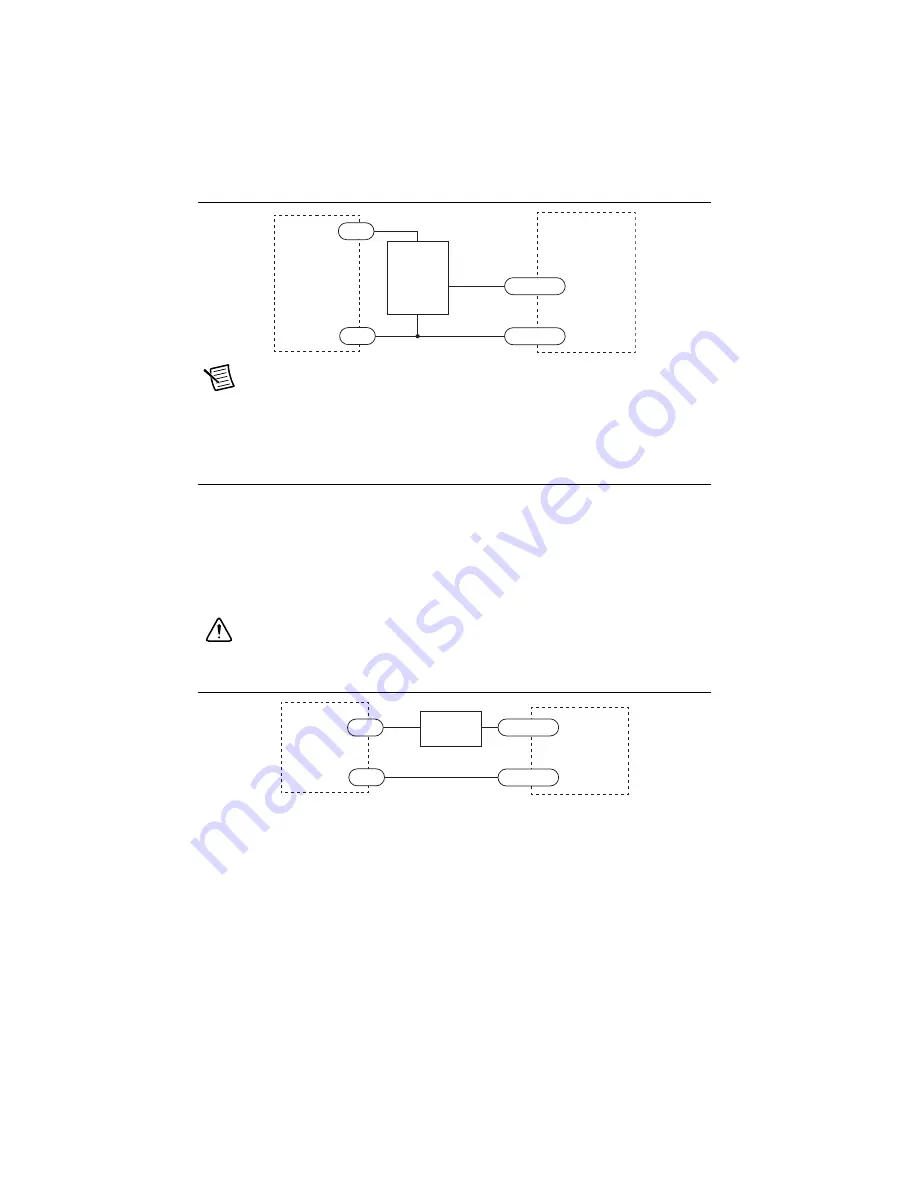
Figure 19.
Connecting a PNP Type Proximity Sensor to an Input
Note
When the proximity sensor activates, the input closes.
When a device is configured to accept streaming commands through the NI Stepper
Configuration Utility, the EN input is reconfigured to accept an input from a home switch.
Connecting the Digital Output
The NI ISM-7413 has a digital output labeled OUT. You can use this output to automatically
control a motor brake or signal fault conditions. You can also use it to drive LEDs, relays, and
the inputs of other electronic devices like PLCs. The positive collector (OUT+) and negative
emitter (OUT-) terminals of the output transistor are available at the connector. This allows you
to configure the output for current sourcing or sinking.
Diagrams of each type of connection follow.
Caution
Do not connect the output to more than 30 VDC. The current through the
output terminal must not exceed 100 mA.
Figure 20.
Sinking Output
5-24 VDC
Power
Su
pply
–
+
EN/IN
3
–
EN/IN
3
+
O
u
tp
u
t
I
S
M-741
3
NPN
Proximity
S
en
s
or
–
+
5-24 VDC
Power
Su
pply
–
+
OUT–
OUT+
Lo
a
d
I
S
M-741
3
Summary of Contents for ISM-7413
Page 1: ...ISM 7413...


