background image

Getting Started NI ISM-7411/7412/7413 Integrated Steppers

|

© National Instruments

|

9

Position

— Specify the target position, in the axis will be driven toward. 

Velocity

— Specific the maximum velocity of the move in steps/s.

Acceleration

— Specify the maximum rate of acceleration when starting the move, 

in Units/s

2

.

Deceleration

— Specify the maximum rate of deceleration when stopping the move, 

in Units/s

2

.

When all the settings are configured, run the VI, and click the 

Start Move

 button. The motor 

should turn according to the configured move. Click the 

Stop Move 

button to stop the motor, 

and the 

Stop VI

 when you are finished with the project.

Understanding the Example

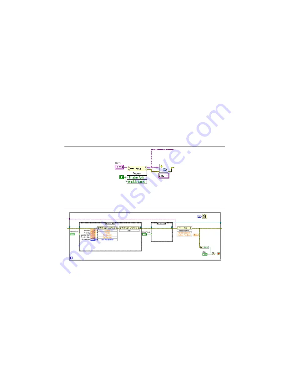
The example VI begins by creating a motion resource and using an invoke node to enable the 
drive.

Figure 4.  

Creating a Motion Resource

When the move is started, all of the configured parameters are written with a property node. The 
position feedback is read with an invoke node and displayed.

Figure 5.  

Applying the Move Parameters

Summary of Contents for ISM-7411

Page 1: ...tep 1 Connect the NI PS 12 13 Power Supply 3 Step 2 Connect the Integrated Stepper to the Network 4 Step 3 Verify the Connections 8 Using the ISM with SoftMotion 8 Running the Example 8 Understanding the Example 9 Worldwide Support and Services 10 What You Need to Get Started You need the following items to get started Hardware 12 VDC to 70 VDC power supply NI PS 12 NI part number 748906 01 or NI ...

Page 2: ...To access this help file from LabVIEW select Help LabVIEW Help then expand the LabVIEW NI SoftMotion Module book on the Contents tab LabVIEW Help Use the LabVIEW Help to access information about LabVIEW programming concepts step by step instructions for using LabVIEW and reference information about LabVIEW VIs functions palettes menus tools properties methods events dialog boxes and so on The LabV...

Page 3: ...f the V wire to the corresponding terminal on the included power connector Tighten the screw to ensure a secure connection 4 Connect one end of a 1 02 mm to 0 81 mm diameter 18 20 AWG gauge stranded wire to the V terminal on the power supply 5 Connect the free end of the V wire to the corresponding terminal on the included power connector Tighten the screw to ensure a secure connection 6 Insert th...

Page 4: ...ress for each switch setting is shown in the table below Settings 1 through E can be changed using the NI Stepper Configuration Utility software Setting 0 is always 10 10 10 10 the universal recovery address Setting F is DHCP which commands the device to get an IP address from a DHCP server on the network The IP address automatically assigned by the DHCP server may be dynamic or static depending o...

Page 5: ...mething else by the DHCP server at another time Once you ve chosen an appropriate IP address for your device set the rotary switch according to the address table above If none of the default addresses are acceptable for your network you can enter a new table of IP addresses using the NI Stepper Configuration Utility If your network uses addresses starting with 192 168 0 the most common subnet you ...

Page 6: ... Utility can find your device using the Drive Discovery feature as long as your network isn t too large When the device connected to the network is powered on select Drive Discovery from the Drive menu to launch the Network Interface Dialog dialog box Figure 3 Network Interface Dialog Box Normally Drive Discovery only detects one network interface card NIC and selects it automatically If you are u...

Page 7: ...e device s IP address to this interface card 6 Next enter the subnet mask as 255 255 255 0 7 Leave Default gateway blank This prevents your PC from looking for a router on this subnet Note Because you are connected directly to the device anytime the device is not powered you will receive a small message bubble in the corner of your screen saying The network cable is unplugged Option 3 Use Two Netw...

Page 8: ...ed stepper 3 Open the Drive menu and select Self Test 4 Click Start The motor should begin to move Click Stop to finish the test If the motor failed to move verify the power and network connections Examine the Status LED and refer to the integrated stepper user manual to diagnose any issues Using the ISM with SoftMotion The integrated stepper can be used in a LabVIEW VI as a standard motion resour...

Page 9: ... s2 When all the settings are configured run the VI and click the Start Move button The motor should turn according to the configured move Click the Stop Move button to stop the motor and the Stop VI when you are finished with the project Understanding the Example The example VI begins by creating a motion resource and using an invoke node to enable the drive Figure 4 Creating a Motion Resource Wh...

Page 10: ... Worldwide Support and Services The National Instruments website is your complete resource for technical support At ni com support you have access to everything from troubleshooting and application development self help resources to email and phone assistance from NI Application Engineers Visit ni com services for NI Factory Installation Services repairs extended warranty and other services Visit ...

Reviews: