


Chapter 3
Hardware Overview
3-2
www.ni.com
.
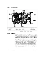
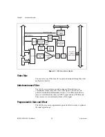
Figure 3-1.
1408 Device Block Diagram
Video Mux
You can select any of the four AC-coupled video inputs through the video
multiplexer circuitry.
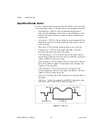
Antichrominance Filter
The 1408 device includes an antichrominance filter that removes
chrominance from a composite color video signal. You can use two
software-selectable antichrominance filters: a 3.58 MHz notch filter to
remove color information from an NTSC signal and a 4.43 MHz notch
filter to remove color information from a PAL signal.
Programmable Gain and Offset
The 1408 device uses programmable gain and offset circuitry to optimize
the input signal range.
PCI Interface
and
Scatter-Gather
DMA Controllers
25-Pin DSUB Connector
BNC
PCI Bus
PCLK,
HSYNC,
VSYNC
Mux
Generated
PCLK,
HSYNC,
VSYNC
CSYNC
Mux
Genlock and
Synchronization
Circuitry
VCO and
PLL
Circuitry
Pixel
Aspect
Ratio
Circuitry
Four External Triggers
VSYNC
and HSYNC
PCLK
Trigger Control
and Mapping
Circuitry
Acquisition and
Region of Interest
Control
FIFOs
8-Bit A/D
and LUT
Programmable
Gain and
Offset
RTSI Bus
External PCLK,
VSYNC, and HSYNC
Antichrominance
Filter
Video Mux
Video 0, 1, 2, 3
Video 0
External CSYNC
Video
In


