Chapter 7
Digital I/O
DAQ-STC Technical Reference Manual
7-2
©
National Instruments Corporation
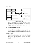
Figure 7-1.
DIO Simplified Model
The bidirectional DIO<0..7> lines provide a port for 8-bit parallel I/O. When parallel I/O is
not needed, the DIO4/SDIN and DIO0/SDOUT lines provide a port for 8-bit serial I/O. The
signal EXTSTROBE/SDCLK can generate periodic timing for serial I/O or it can act as a
software-controlled handshaking signal for both parallel and serial I/O. The STATUS<0..3>
and CTRL<0..7> lines provide a board-level read and write register.
7.4 Overview of DIO Functions
The DIO module provides two modes of digital I/O operation—parallel mode and serial
mode. In parallel mode, the DAQ-STC transfers data eight bits at a time under software
control. In serial mode, the DAQ-STC transfers data one bit at a time under hardware control,
with software initiating each 8-bit serial transfer. This section discusses the parallel and serial
modes of operation.
7.4.1 Parallel Mode
In parallel I/O mode, eight bits are available for interfacing with a parallel port. The software
outputs data asynchronously to the DIO port by writing the output data to the parallel output
register. The software inputs data asynchronously from the DIO port by reading from the
parallel input register. Software must perform handshaking to ensure that the data is read and
written safely. The EXTSTROBE/SDCLK output is available for simple handshaking
operations.
SERIAL READ
SERIAL WRITE
PARALLEL READ
PARALLEL WRITE
SHIFT IN
SHIFT OUT
DIO4/SDIN
DIO0/SDOUT
EXTSTROBE/SDCLK
DIO<1..3>, DIO<5..7>
CTRL<0..7>
STATUS<0..3>

