Chapter 4
General-Purpose Counter/Timer
DAQ-STC Technical Reference Manual
4-12
©
National Instruments Corporation
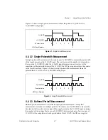
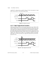
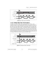
Figure 4-15.
Buffered Retriggerable Single Pulse Generation
4.4.4 Pulse-Train Generation
In the pulse-train generation functions, the counter generates a continuous stream of pulses of
specified interval and duration following the software arm and an optional hardware trigger.
The software arm occurs when software sets the counter arm bit in the DAQ-STC register
map. The following actions are available in pulse-train generation:
•
Specify the pulse parameters in terms of periods of the G_SOURCE input.
•
The G_GATE input can serve as a trigger signal to generate a stream of pulses only after
the active gate edge occurs.
•
The hardware provides an alternate output mode so that G_OUT outputs two counter
TC pulses, instead of a single-long pulse.
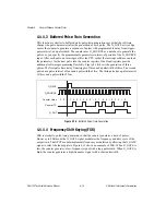
4.4.4.1 Continuous Pulse-Train Generation
This function generates a sequence of pulses with programmable delay from trigger, pulse
interval, and pulsewidth. The counter uses G_SOURCE as a timebase to generate the pulses,
so you specify the programmable parameters in terms of periods of the G_SOURCE input.
Pulse-train generation is implemented in software by loading the pulse parameters into the
counter and load resisters, and by programming the counter to switch load registers on every
counter TC. Figure 4-16 shows the generation of three pulses with a delay from trigger of
three, a pulse interval of four and a pulsewidth of three.
G_SOURCE
G_GATE
G_OUT
Counter Value
Counter TC
1 0
2
3
4
4
4
0
5
2
1
0
3
2
1
0
4
5
2
1
3

