Chapter 3
Analog Output Timing/Control
©
National Instruments Corporation
3-97
DAQ-STC Technical Reference Manual
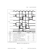
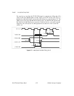
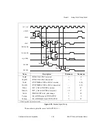
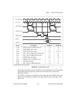
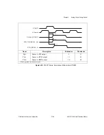
Figure 3-20.
Local Buffer Mode Timing
The numbers in parentheses refer to the number of clock periods that occur at the minimum
and maximum delays, because those parameters are clock-edge driven with possible
additional gate delays.
The AOFEF is recognized by the DAQ-STC at the trailing edge of the TMRDACWR signal.
This leads to the assertion of AOFFRT, which is deasserted on the next rising edge of the
output clock.
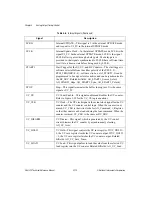
Name
Description
Minimum
Maximum
Tcup
UPDATE_SRC to UPDATE asserted
18
56
Tsup
UPDATE(SRC) pulsewidth
(1)
(1)
Toup
UPDATE(OUT) pulsewidth
(1, 3)
(1.5, 3.5)
Tcupd
OUT_CLK to UPDATE(OUT) deasserted
12
38
Tctwr
OUT_CLK to TMRDACWR asserted
11
34
Twr
TMRDACWR pulsewidth
(2, 3)
(2, 3)
Twrrt
TMRDACWR to AOFFRT asserted
2
6
Tdafrt
AOFFRT pulsewidth
(1)
(1)
Tcrtd
OUT_CLK to AOFFRT deasserted
10
32
All timing values are in nanoseconds.
UPDATE_SRC
UPDATE(SRC)
UPDATE(OUT)
TMRDACWR
AOFEF
AOFFRT
OUT_CLK
Twrrt
Tdafrt
Tctwr
Tctwr
Twr
Twr
Tcup
Toup
Tcupd
Tcup
Toup
Tcupd
Tcup
Tsup
Tcup
Tsup
Tcrtd


