NAPCO StarLink Connect Series Getting Started Download Page 19

NAPCO StarLink Fire:  Getting Started Guide 

19


333 Bayview Avenue 

Amityville, New York 11701 

For Sales and Repairs, (800) 645-9445 

For Technical Service, (800) 645-9440 or visit us at 

http://tech.napcosecurity.com/ 

(Note:  Technical Service is for security professionals only)


Publicly traded on NASDAQ      Symbol: NSSC 

© NAPCO 2017 

The NAPCO 

SLE-CDMA-FIRE 

and 

SLECDMA-CFB 

Commercial Fire radios, fully compliant with the 2010 edition of 

NFPA 72, are approved as fire alarm communicators.  The capability of indicating and communicating signal failures to the 
central station within 5 minutes of an outage allows the 

SLE-CDMA-FIRE 

or 

SLECDMA-CFB

 to replace existing tele-

phone lines.   


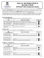
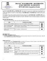
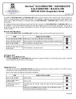
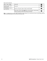
The following testing guide is intended to assist with the AHJ inspection of a 

SLE-CDMA-FIRE 

or 

SLECDMA-CFB

 Fire ra-

dio installation.  All required testing procedures are described, followed by the correct system responses.  Ensure that in 
cases where a radio trouble output is connected to an input on the FACP, the fire control panel properly annunciates the 
trouble condition. 
 

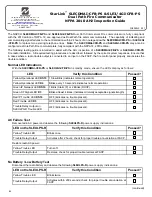
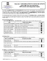
Normal LED Indications 


With the SLE radio in standby mode, ensure the LEDs display as follows: 
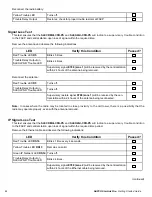


AC Failure Test 
No Battery / Low Battery Test 

 The 

SLE-CDMA-FIRE 

and 

SLECDMA-CFB 

models are powered directly from the FACP power supply; radio AC 

Failure and Battery Failure tests are not required.   
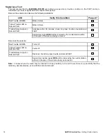
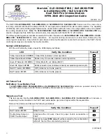
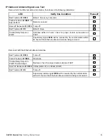


Signal Loss Test 

This test ensures that the 

SLECDMA-CFB-PS

 will indicate a supervisory trouble condition to the FACP and cen-

tral station upon loss of signal within the required time period.   


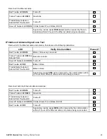
Remove the antenna and observe the following indications: 


(continued) 


WI2177B  1/17 

StarLink

 SLE-CDMA-FIRE - SLECDMA-CFB  

& SLE-GSM-FIRE - SLE3/4G-CFB    

NFPA 2010 AHJ Inspection Guide


LED 

Verify this Condition 

Passed? 

Yellow Operational LED 

D4


Blinks every 10 seconds (indicates normal operation). 


Green RF Signal LED 

D3


Blinks at least 4 times (indicates minimally acceptable signal strength).   

Red Trouble LED 

D5


OFF (indicates no trouble present). 


LED 

Verify this Condition 

Passed? 

Red Trouble LED 

D5


Blinks 5 times. 


Yellow Trouble LED on  
SLE-ULPS-R 

Blinks 4 times. 


Trouble Relay Output on  
SLE-ULPS-R 

Activates within 5 minutes; check for proper trouble annunciation at 
FACP 


Supervisory signal 

E356 

will be received by the central station within  

5 minutes of the antenna being removed. 


Yellow Trouble LED on the 
SLEULPS-R 

OFF (indicates no trouble present). 


Summary of Contents for StarLink Connect Series

Page 1: ...ng for Dial Capture DACT Installations Quick Start NOC Configuration and Communicator Wiring for a Panel Relay Triggered Installation AHJ Testing of Communicator Take the guesswork out of testing the...

Page 2: ...2 NAPCO StarLink Fire Getting Started Guide...

Page 3: ...rLink Fire Dual Path models have an I in the part number indicating Internet The requirement for Dual Path is typicality determined by the municipality or the local AHJ Note that you may purchase and...

Page 4: ...4 NAPCO StarLink Fire Getting Started Guide...

Page 5: ...NAPCO StarLink Fire Getting Started Guide 5...

Page 6: ...6 NAPCO StarLink Fire Getting Started Guide...

Page 7: ...NAPCO StarLink Fire Getting Started Guide 7...

Page 8: ...8 NAPCO StarLink Fire Getting Started Guide...

Page 9: ...Type the Device ID Radio ID into the Unit ID field for the respective device Service Plan then click Go NAPCO Remote Services ComNet Activation Guide WI2113BLF 3 18 333 Bayview Avenue Amityville New...

Page 10: ...Guide 4 Click the Click for Details text to review the details of the service plan 5 Click Add to add the service plan to the shopping cart 6 Click New for a new subscriber or Existing to add the devi...

Page 11: ...iew the subscriber information then click Add to Cart 9 Click Close if you do not want additional features 10 In the Shopping Cart see below click Process Order to complete the activation process John...

Page 12: ...12 NAPCO StarLink Fire Getting Started Guide...

Page 13: ...connections permitted RED GREEN 9LE10KHARN installed in FACP Blue Red normally closed relay open on trouble Red Black normally open relay short on alarm To FACP Ground Common Terminal not earth groun...

Page 14: ...of radio firmware radio jumper X5_J1 must be removed 2 Note Upon ac va on of the fire alarm relay short on black and red harness wires an alarm signal will be transmi ed to the central sta on Upon ac...

Page 15: ...EDs display as follows AC Failure Test Remove radio AC power and observe the following SLEULPS R power supply indications Restore radio AC power No Battery Low Battery Test Disconnect the radio batter...

Page 16: ...perly even with the antenna removed LED Verify this Condition Passed Red Trouble LED D5 Blinks 5 times Yellow Trouble LED on SLE ULPS R Blinks 4 times Trouble Relay Output on SLE ULPS R Activates with...

Page 17: ...EDs display as follows AC Failure Test Remove radio AC power and observe the following SLEULPS R power supply indications Restore radio AC power No Battery Low Battery Test Disconnect the radio batter...

Page 18: ...erly even with the antenna removed LED Verify this Condition Passed Red Trouble LED D5 Blinks 5 times Yellow Trouble LED on SLE ULPS R Blinks 4 times Trouble Relay Output on SLE ULPS R Activates withi...

Page 19: ...dio in standby mode ensure the LEDs display as follows AC Failure Test No Battery Low Battery Test The SLE CDMA FIRE and SLECDMA CFB models are powered directly from the FACP power supply radio AC Fai...

Page 20: ...possibility that the radio may operate properly even with the antenna removed Red Trouble LED D5 Turns off Yellow Trouble LED on SLE ULPS R Turns off Trouble Relay Output on SLE ULPS R Restores check...

Page 21: ...SLECDMA CFB in standby mode ensure the LEDs display as follows AC Failure Test No Battery Low Battery Test The SLE CDMA FIRE and SLECDMA CFB models are powered directly from the FACP power supply rad...

Page 22: ...possibility that the radio may operate properly even with the antenna removed Red Trouble LED D5 Turns off Yellow Trouble LED on SLE ULPS R Turns off Trouble Relay Output on SLE ULPS R Restores check...

Page 23: ...tions With the SLECDMAI CFB PS or SLE3 4GI CFB PS in standby mode ensure the LEDs display as follows AC Failure Test Remove radio AC power and observe the following SLEULPS R power supply indications...

Page 24: ...cable and observe the following indications continued Yellow Trouble LED Turns off Trouble Relay Output Restores check for proper trouble restoral at FACP LED Verify this Condition Passed Red Trouble...

Page 25: ...DHCP Red Trouble LED DS16 Turns off Yellow Trouble LED DS15 Slow blink Trouble Relay Output on SLEULPS R Trouble LED Turns off Supervisory restore signal R356 will be received by the central station w...

Page 26: ...26 NAPCO StarLink Fire Getting Started Guide...

Page 27: ...tions With the SLECDMAI CFB PS or SLE3 4GI CFB PS in standby mode ensure the LEDs display as follows AC Failure Test Remove radio AC power and observe the following SLEULPS R power supply indications...

Page 28: ...cable and observe the following indications continued Yellow Trouble LED Turns off Trouble Relay Output Restores check for proper trouble restoral at FACP LED Verify this Condition Passed Red Trouble...

Page 29: ...DHCP Red Trouble LED DS16 Turns off Yellow Trouble LED DS15 Slow blink Trouble Relay Output on SLEULPS R Trouble LED Turns off Supervisory restore signal R356 will be received by the central station w...

Page 30: ...30 NAPCO StarLink Fire Getting Started Guide...

Page 31: ...Failure tests are not required Signal Loss Test This test ensures that the SLE CDMAI FIRE SLE GSMI FIRE or SLECDMAI CFB SLE3 4GI CFB will indicate a supervisory trouble condition to the FACP and centr...

Page 32: ...uble restoral at FACP Supervisory restore signal R788 zone 1 will be received by the cen tral station within 24 hours of the antenna being reconnected LED Verify this Condition Passed Red Trouble LED...

Page 33: ...by the central station within 24 hours of the Ethernet cable and antenna being reconnected Green IP Network LED DS14 1 Blink Static IP or 2 Blinks DHCP Red Trouble LED D5 Turns off LED Verify this Co...

Page 34: ...34 NAPCO StarLink Fire Getting Started Guide...

Page 35: ...D Indications With the unit in standby mode ensure the LEDs display as follows AC Failure Test No Battery Low Battery Test The SLE CDMAI FIRE SLE GSMI FIRE and SLECDMAI CFB SLE3 4GI CFB models are pow...

Page 36: ...rouble restoral at FACP Supervisory restore signal R788 zone 1 will be received by the cen tral station within 6 hours of the antenna being reconnected LED Verify this Condition Passed Red Trouble LED...

Page 37: ...ed by the central station within 6 hours of the Ethernet cable and antenna being reconnected Green IP Network LED DS14 1 Blink Static IP or 2 Blinks DHCP Red Trouble LED D5 Turns off LED Verify this C...

Page 38: ...38 NAPCO StarLink Fire Getting Started Guide...

Page 39: ...94MHz and 1850 1990MHz bands and are designed to minimize loss and maximize gain The antenna is foam filled for vibration stabilization and long lasting performance in extreme conditions A UV stable p...

Page 40: ...40 NAPCO StarLink Fire Getting Started Guide...

Reviews: