2
power supplied from two wires intended to be hidden within
the mounting surface. These two wires are connected to a
power supply that can be plugged into any standard
120VAC outlet, such as in a basement or other distant loca-
tion.
Note:
Power wires are polarized
, and MUST be in-
stalled as detailed in the installation instructions that follow.
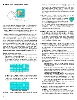
To ensure a continuous wireless connection between the IBR-
ITAB keypad and the IBR-WIFI-MOD or ISEE-WAP, select a lo-
cation for the Charging Station that is within a reasonable dis-
tance from the IBR-WIFI-MOD or ISEE-WAP. Choose a location
as high above ground level as practical, keeping in mind that
metal objects may adversely affect reception. Although wood and
wallboard construction will have little effect upon signal strength,
concrete or brick can reduce signal strength by up to 35%, while
steel-reinforced concrete or metal lath and plaster can reduce sig-
nal strength as much as 90%.
Mount the IBR-ITAB keypad Charging Station indoors only, and
avoid high condensation areas such as bathrooms. Avoid mount-
ing in locations where direct sunlight or bright light shines directly
on the screen.
CHARGING STATION INSTALLATION
HOLLOW WALL
If installing into a 3-gang box, see instructions to the right. To
secure the Wall Mounting Plate directly to a hollow dry wall or
similar surface, proceed as follows:
1. Select the mounting location preferably at eye level for easy
viewing by the user. Select a mounting location that allows
the power wires to be hidden within the mounting surface.
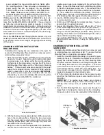
Furthermore, in the image below, note how the "Wire Hole in
Wall Mounting Plate" aligns with the "Wire Hole in Mounting
Surface". The two power wires are connected to the power
supply that is plugged into any standard 120VAC outlet lo-
cated in a basement or other distant location.
IMPORTANT
:
The positive power supply wire is marked with red heat
shrink tubing; be sure not to dislodge this red marking when
routing wires, as polarity MUST be maintained.
2. With the final mounting location selected, drill the power wire
hole in the mounting surface. Snake the two power wires
from the power supply source location into the
interior
of the
mounting surface (wall), then out through the power wire
hole drilled in the mounting surface.
3. Using wire nuts or connectors appropriate for the installation,
connect the red wire from the Wall Mounting Plate to the
positive power supply wire marked with the red heat shrink
tubing. Connect the black wire from the Wall Mounting Plate
to the other black power supply wire. If the red heat shrink
tubing was dislodged and you are uncertain as to the polar-
ity, use a voltmeter to determine the polarity. Push wires
into the power wire hole in the mounting surface, leaving the
Wall Mounting Plate flush against the mounting surface.
4. Use the Wall Mounting Plate as a template, marking the 6
screw holes with a pencil.
5. Drill 6 holes 3/16" diameter for mollies (anchors). Tap mol-
lies (anchors) into wall with hammer.
6. Secure Wall Mounting Plate to wall with six #6 x 1" long
sheet metal Phillips flat head Type A screws (part SC461).
7. To hide the screw heads installed in the previous step, a Fin-
ishing Cover Plate (HW1854) is provided. Firmly press the
Finishing Cover Plate into the Wall Mounting Plate until the
top and bottom snaps fully engage.
To enroll the IBR-ITAB into the security system using an
IBR-WIFI-MOD see WI1942; if using an ISEE-WAP see
WI2049.
CHARGING STATION INSTALLATION
3-GANG BOX
If installing the Wall Mounting Plate directly to a hollow dry wall
or similar surface, see instructions at left. To secure the Wall
Mounting Plate to a 3-gang box, proceed as follows:
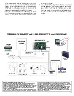
1. Select the mounting location preferably at eye level for easy
viewing by the user. Reference the diagram below; with the
3-gang box installed, notice how the Wall Mounting Plate
two power wires are intended to run through the largest hole
in the Gang Box Insert into the 3-Gang Box. These two
power wires are connected to the two power wires from the
power supply that are routed into the 3-Gang Box. The
power supply is plugged into any standard 120VAC outlet
located in a basement or other distant location.
2. With the 3-Gang Box installed, snake the two power supply
wires from the transformer power source location into the 3-
Gang Box.
IMPORTANT
: The positive power supply wire is marked
with red heat shrink tubing; be sure not to dislodge this red
marking when routing wires, as polarity MUST be main-
tained.
3. Run the Wall Mounting Plate two power wires through the
largest hole in the Gang Box Insert and into the 3-Gang Box.
Using wire nuts or connectors appropriate for the installation,
Hollow Wall Installations
"Wire
Hole in
Mounting
Surface"
"Wire Hole
in Wall
Mounting
Plate"
(9HW1836ASSY)
Wall Mounting
Plate
(SC461) #6 x 1" long
sheet metal Phillips
flat head Type A
screws (6)*
(HW1854)
Finishing
Cover
Plate
3-Gang Box Installations
(SC523)
Screws (6)
(HW1848)
Gang Box
Insert
3-Gang Box
(Installer provided)
(SC652) #6 x 1" long
Hi-Low Phillips flat
head screws (6)
(HW1854)
Finishing
Cover Plate
(9HW1836ASSY)
Wall Mounting
Plate


