


X
GEM-P1664 Programming Instructions
L
NAPCO Security Systems
Page 44
WI1423A 1/06
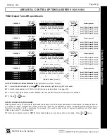
NOTES:
(A) 50ms Loop Response only available for zones 1-8.
(B) 2-wire Smoke Detectors only available for zones 7 & 8, and
Fire
must also be selected.
(C) If Fire Alarm Verification is selected, then Fire must also be selected.
DEFAULTS:
The zone options indicated are automatically set after exiting the Easy Menu Driven Mode.
--Priority, Selective Bypass, Alarm Output, Auto Reset, Swinger Shutdown
and
Zone Area 1
are enabled for the total number of zones entered in “
# OF ZONES IN AREA1 ENTER # ZONES
”.
--Alarm Telco 1
is enabled for the zone number(s) entered in “
REPORT ALL ZONES TO CENTRAL ZONES? Y/N
”.
--Entry/Exit 1
and
Chime
are enabled for the zone number(s) entered in “
ENTRY/EXIT ZONES ENTER ZONE #
”.
--Exit/Entry Follower
and
Interior Bypass
are enabled for the zone number(s) entered in “
INTERIOR ZONES ENTER ZONE #
”.
--Pulse Alarm Output
is enabled for the zone number(s) entered in “
FIRE ZONES ENTER ZONE #
” or “
2-WIRE FIRE ZNS ENTER ZONE #
”.
--Fire
is enabled for the zone number(s) entered in “
FIRE ZONES ENTER ZONE #
”.
--
2-Wire Smoke Detector is enabled for the zone number(s) entered in “
2-WIRE FIRE ZNS ENTER ZONE #
”.
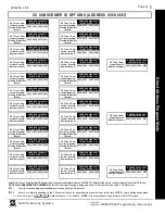
ZONE OPTIONS - ZONES 17 TO 32 (ADDRESS 1029-1144)
Direct
A
d
dress Program Mode
ZONE OPTIONS
ZONES 29-32
LEFT DATA VALUES
ADDRESS
ZONES 25-28
RIGHT DATA VALUES
ZONES 21-24
LEFT DATA VALUES
ADDRESS
ZONES 17-20
RIGHT DATA VALUES
ZN32 ZN31 ZN30 ZN29 L ADDR R ZN28 ZN27 ZN26 ZN25 ZN24 ZN23 ZN22 ZN21 L ADDR R ZN20 ZN19 ZN18 ZN17
Priority
8
4
2
1
1093
8
4
2
1
8
4
2
1
1029
8
4
2
1
Priority with Bypass
8
4
2
1
1094
8
4
2
1
8
4
2
1
1030
8
4
2
1
Auto-Bypass
8
4
2
1
1095
8
4
2
1
8
4
2
1
1031
8
4
2
1
Selective Bypass
8
4
2
1
1096
8
4
2
1
8
4
2
1
1032
8
4
2
1
Keyswitch Arming
8
4
2
1
1097
8
4
2
1
8
4
2
1
1033
8
4
2
1
Auto-Bypass Re-entry
8
4
2
1
1098
8
4
2
1
8
4
2
1
1034
8
4
2
1
Pre-Alarm Warning
8
4
2
1
1099
8
4
2
1
8
4
2
1
1035
8
4
2
1
Never Arm
8
4
2
1
1100
8
4
2
1
8
4
2
1
1036
8
4
2
1
24-Hour Zone
8
4
2
1
1101
8
4
2
1
8
4
2
1
1037
8
4
2
1
Alarm Output
8
4
2
1
1102
8
4
2
1
8
4
2
1
1038
8
4
2
1
Pulsed Alarm Output
8
4
2
1
1103
8
4
2
1
8
4
2
1
1039
8
4
2
1
PGM1 Output
8
4
2
1
1104
8
4
2
1
8
4
2
1
1040
8
4
2
1
PGM2 Output
8
4
2
1
1105
8
4
2
1
8
4
2
1
1041
8
4
2
1
Entry/Exit 1
8
4
2
1
1106
8
4
2
1
8
4
2
1
1042
8
4
2
1
Entry/Exit 2
8
4
2
1
1107
8
4
2
1
8
4
2
1
1043
8
4
2
1
Exit/Entry Follower
8
4
2
1
1108
8
4
2
1
8
4
2
1
1044
8
4
2
1
Auto Reset
8
4
2
1
1109
8
4
2
1
8
4
2
1
1045
8
4
2
1
Swinger Shutdown
8
4
2
1
1110
8
4
2
1
8
4
2
1
1046
8
4
2
1
Chime
8
4
2
1
1111
8
4
2
1
8
4
2
1
1047
8
4
2
1
Abort Delay
8
4
2
1
1112
8
4
2
1
8
4
2
1
1048
8
4
2
1
Power-up Delay
8
4
2
1
1113
8
4
2
1
8
4
2
1
1049
8
4
2
1
Day Zone Open
8
4
2
1
1114
8
4
2
1
8
4
2
1
1050
8
4
2
1
Day Zone Short
8
4
2
1
1115
8
4
2
1
8
4
2
1
1051
8
4
2
1
Alarm on Day Zone
8
4
2
1
1116
8
4
2
1
8
4
2
1
1052
8
4
2
1
Alarm Telco 1
8
4
2
1
1117
8
4
2
1
8
4
2
1
1053
8
4
2
1
Alarm Restore 1
8
4
2
1
1118
8
4
2
1
8
4
2
1
1054
8
4
2
1
Trouble Telco 1
8
4
2
1
1119
8
4
2
1
8
4
2
1
1055
8
4
2
1
Trouble Restore 1
8
4
2
1
1120
8
4
2
1
8
4
2
1
1056
8
4
2
1
Alarm Telco 3
8
4
2
1
1121
8
4
2
1
8
4
2
1
1057
8
4
2
1
Alarm Restore 3
8
4
2
1
1122
8
4
2
1
8
4
2
1
1058
8
4
2
1
Trouble Telco 3
8
4
2
1
1123
8
4
2
1
8
4
2
1
1059
8
4
2
1
Trouble Restore 3
8
4
2
1
1124
8
4
2
1
8
4
2
1
1060
8
4
2
1
No EOL Resistor
8
4
2
1
1125
8
4
2
1
8
4
2
1
1061
8
4
2
1
Trouble on Open
8
4
2
1
1126
8
4
2
1
8
4
2
1
1062
8
4
2
1
Trouble on Short
8
4
2
1
1127
8
4
2
1
8
4
2
1
1063
8
4
2
1
Zone Area 1
8
4
2
1
1128
8
4
2
1
8
4
2
1
1064
8
4
2
1
Zone Area 2
8
4
2
1
1129
8
4
2
1
8
4
2
1
1065
8
4
2
1
Interior (Stay) Bypass
8
4
2
1
1132
8
4
2
1
8
4
2
1
1068
8
4
2
1
Keypad Sounder on Alarm
8
4
2
1
1133
8
4
2
1
8
4
2
1
1069
8
4
2
1
Fire (C)
8
4
2
1
1135
8
4
2
1
8
4
2
1
1071
8
4
2
1
Fire Alarm Verification
(C)
8
4
2
1
1136
8
4
2
1
8
4
2
1
1072
8
4
2
1
Zone ANDing Group 1
8
4
2
1
1138
8
4
2
1
8
4
2
1
1074
8
4
2
1
Zone ANDing Group 2
8
4
2
1
1139
8
4
2
1
8
4
2
1
1075
8
4
2
1
Zone ANDing Group 3
8
4
2
1
1140
8
4
2
1
8
4
2
1
1076
8
4
2
1
Zone ANDing Group 4
8
4
2
1
1141
8
4
2
1
8
4
2
1
1077
8
4
2
1
Sensor Watch
8
4
2
1
1142
8
4
2
1
8
4
2
1
1078
8
4
2
1
RESERVED
8
4
2
1
1143
8
4
2
1
8
4
2
1
1079
8
4
2
1
Chime 2
8
4
2
1
1144
8
4
2
1
8
4
2
1
1080
8
4
2
1
When the Easy Program Menu is used, these features are enabled by default.
Enabled when "Enable SIA CP-01 Features?" is activated (Answer "Yes" in the EZ Programming Menu).
Zone Area 3
8
4
2
1
1130
8
4
2
1
8
4
2
1
1066
8
4
2
1
Zone Area 4
8
4
2
1
1131
8
4
2
1
8
4
2
1
1067
8
4
2
1
Step 1
Step 4 Step 4
Step 4 Step 4
Step 2
Step 2
Step 2
Step 2
See Steps listed at
bottom of page 44