NAPCO GEMINI GEM-P1664 Programming Instructions Manual Download Page 33

L

 NAPCO Security Systems  

X

  GEM-P1664 Programming Instructions 


Page 33


WI1423A  1/06 

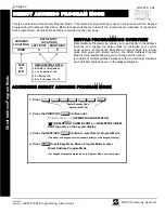
Default for Group Zone Report Codes depends on Easy Menu Question “RCVR. FORMAT”. 

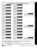
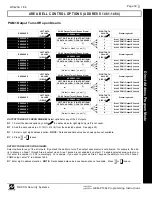
CS ZONE REPORTING OPTIONS (ADDRESS 0720-0783) 

ADDRESS 0720-0727  

CONTROL PANEL ZONES REPORT CODE  

ZONE 1   ZONE 2   ZONE 3   ZONE 4   ZONE 5   ZONE 6   ZONE 7   ZONE 8  

0720  

0721 

0722 

0723 

0724 

0725 

0726 


0727 

ADDRESS 0728-0731  

ZONES REPORT CODE  

ZONE 9  ZONE 10  ZONE 11  ZONE 12  

0728  

0729 

0730 


0731 

ADDRESS 0732-0735  

ZONES REPORT CODE  

ZONE 13  ZONE 14  ZONE 15  ZONE 16  

0732  

0733 

0734 


0735 

ADDRESS 0744-0747  

ZONES REPORT CODE  

ZONE 25  ZONE 26  ZONE 27  ZONE 28  

0744  

0745 

0746 


0747 

ADDRESS 0748-0751  

ZONES REPORT CODE  

ZONE 29  ZONE 30  ZONE 31  ZONE 32  

0748  

0749 

0750 


0751 

ADDRESS 0736-0739  

ZONES REPORT CODE  

ZONE 17  ZONE 18  ZONE 19  ZONE 20  

0736  

0737 

0738 


0739 

ADDRESS 0740-0743  

ZONES REPORT CODE  

ZONE 21  ZONE 22  ZONE 23  ZONE 24  

0740  

0741 

0742 


0743 

ZONE REPORT 

CODE OPTIONS  

LEFT 

RIGHT 


DATA ENTRIES  

NOTE:  

If “Zone Doubling” (Address 1423) is 

not 

enabled, then Zones 1-8 are included in the control panel and 

Zones 9-64 are EZM Zones.  If “Zone Doubling” is enabled, then Zones 1-16 are included in the control panel and 
Zones 17-64 are EZM Zones.  See Address 1455-1468 to enable “EZM Group Options”. 

PULSE EVENT CODE

 will be the first digit of the 2 digit reporting code.  The second digit will be the 

second digit of the reporting zone.  For example, for zone 9 (address 0728), if the right digit is “3", then 
the reporting code is ”39".  For example, for zone 15 (address 0734), if the right digit is “4", then the re-
porting code is ”45". 

MODEM CODES

 determine the zone types reported for the following formats: SIA and ADEMCO Point ID. 

1. Select the desired Modem Code for each zone from the table shown. 

2. Press 

U

 or 

D

 to save. 

Direct A

d

dress 

Program 

Mode 

DATA 

ENTRIES 


MODEM CODE 

LEFT 


Fire 

Panic 

Burglary 

Hold up 

Gas Alarm 

Heat Alarm 

Auxiliary Alarm 

24 Hour Auxiliary 

ADDRESS 0752-0759  

CONTROL PANEL ZONES REPORT CODE  

ZONE 33  ZONE 34  ZONE 35  ZONE 36  ZONE 37  ZONE 38 ZONE 39 ZONE 40 

0752  

0753 

0754 

0755 

0756 

0757 

0758 


0759 

ADDRESS 0760-0763  

ZONES REPORT CODE  

ZONE 41 ZONE 42 ZONE 43 ZONE 44 

0760  

0761 

0762 


0763 

ADDRESS 0764-0767  

ZONES REPORT CODE  

ZONE 45 ZONE 46 ZONE 47 ZONE 48 

0764  

0765 

0766 


0767 

ADDRESS 0776-0779  

ZONES REPORT CODE  

ZONE 57  ZONE 58 ZONE 59 ZONE 60 

0776  

0777 

0778 


0779 

ADDRESS 0780-0783 

ZONES REPORT CODE  

ZONE 61  ZONE 62 ZONE 63 ZONE 64 

0780  

0781 

0782 


0783 

ADDRESS 0768-0771  

ZONES REPORT CODE  

ZONE 49 ZONE 50 ZONE 51 ZONE 52 

0768  

0769 

0770 


0771 

ADDRESS 0772-0775  

ZONES REPORT CODE  

ZONE 53  ZONE 54 ZONE 55 ZONE 56 

0772  

0773 

0774 


0775 

Summary of Contents for GEMINI GEM-P1664

Page 1: ...ck Start for GEM K3DGTL 1 Refer to the wiring diagram connect Siren Aux Power PGM Output Remote Bus Earth Ground Zone and Tele phone Wiring NOTE See Installation Instructions WI1424 2 Connect AC power...

Page 2: ...al are depicted using the K Se ries keypads the manual applies to both the classic and the K Series keypads Program Mode is the same for both keypads only the button names have changed as follows The...

Page 3: ...verview 20 Accessing Direct Address Program Mode 20 Keypad Address Program Mode Display 21 Direct Address Program Mode Keypad Commands 21 Direct Address Programming Example 22 Conventions Used in this...

Page 4: ...gram Mode Keypad Programming The Direct Address Program Mode is an extension of the Dealer Program Mode wherein data is entered at the keypad by specific location This mode is accessed from the Easy M...

Page 5: ...4 Hour Zones in Area 1 Chime Zones in Area 1 Chime 2 Zones in Area 1 Exit Entry2 Zones in Area 1 50mS Loop Response Zones Note 750mS is required for Loop Response time in UL installations Aux Output A...

Page 6: ...ire Zones in Area 1 Appears for New Panel Only Enter the zone number of any zones which are to be used as Fire Zones both 2 wire 4 wire or wireless Valid entries are from 01 to 64 Directly enter each...

Page 7: ...ct pulsating tone when zone is faulted Exit Entry2 Zones in Area 1 New Program Only Enter the zone numbers of zones to be used as Exit Entry 2 zones Valid entries are from 01 to 64 Directly enter each...

Page 8: ...s the NEXT YES button to enable Press the PRIOR NO button to continue The SIA CP 01 Features are designed to reduce the incidence of false alarms See WI1424 Installer Pro gramming Quick Reference Char...

Page 9: ...User Codes with Area 1 4 Options Press R once to set the cursor to the User Code Use the number buttons 1 through 9 to enter a code from 3 to 6 digits Enter up to 6 digits 4 digits is recommended in t...

Page 10: ...s is normally used to activate a door strike while an area is disarmed Also program Access Control on PGM2 Output Address 0719 and PGM2 Output Access Control Timeout Address 0711 Ambush There are two...

Page 11: ...tons on a system each reporting to a Central Station or a pager and or annunciating on a keypad the key fob zone number with description location To assign a key fob to a zone program the keyfob as yo...

Page 12: ...ess the U button Data entry is not allowed NOTE Enter Easy Menu Driven Program Mode to program system again Cold Start Erases Entire Program This erases the entire program including Dealer Program by...

Page 13: ...structions Fire Zones Appears for New Panel Only Enter the zone number of any Fire Zones both 2 wire 4 wire or wireless Valid entries are from 01 to 64 Directly enter each zone number including leadin...

Page 14: ...the zone numbers of zones to be used as Exit Entry zones Valid entries are from 01 to 64 Directly enter each zone number including leading zeros Press U to save and repeat for any additional zone s pr...

Page 15: ...NEXT YES button to program all zones except 24 Hr fire zones for No End Of Line Resistor Press the PRIOR NO button to continue NOTE Do not program this feature for UL Installations Enable Telco Line F...

Page 16: ...Options for each code Refer to the tables below for available data entries for User Options Press R once to set cursor to the User Number and enter the desired User Number Press R once again to set th...

Page 17: ...s and U save Notes 1 For User Code press G 0 for Blank Space 2 For User Options press 0 for Blank Space 28 INTERIOR BYPASS FIRE TBL SYS TBL CHIME INTERIOR BYPASS FIRE TBL SYS TBL CHIME Quick Enroll Me...

Page 18: ...nes can be assigned providing multiple wireless panic buttons on a system each reporting to the Central Station or a pager and or annunciating on a keypad the key fob zone number with description loca...

Page 19: ...s C to silence the keypad Direct Entry 33 INTERIOR BYPASS FIRE TBL SYS TBL CHIME INTERIOR BYPASS FIRE TBL SYS TBL CHIME rE ZONE DESCRIPTIONS GEM K3DGTL cannot be used to enter Zone Descriptions To ent...

Page 20: ...to change all the options It consists of multiple address locations with two data entry locations each left and right as shown in the adjacent diagram ACCESSING DIRECT ADDRESS PROGRAM MODE LEFT DIGIT...

Page 21: ...GTL GEM K3DGTL Keypads To access press C in Dealer Program Mode 1 Toggle Cursor to 4 digit ad dress field using the R button 2 Enter address Number directly using number buttons 0 9 3 Enter Data direc...

Page 22: ...ith your program ENTRY TOTAL PRESS N KEYPAD DISPLAYS 8 4 2 1 blank 0 8 4 2 1 1 1 8 4 1 2 2 2 8 4 3 3 3 8 2 1 4 4 4 8 2 5 5 5 8 1 6 6 6 8 7 7 7 4 2 1 8 8 8 4 2 9 9 9 4 1 10 G 0 0 4 11 G 1 B 2 1 12 G 2...

Page 23: ...h address CONVENTIONS USED IN THIS MANUAL The Keypad Programming Worksheets in the back are provided as an address programming reference to help the installer modify his custom default program or to m...

Page 24: ...he programming option data entry from the tables shown 3 Enter the selected data entry in the boxes shown 4 For more information on a programming option refer to the Glossary at the end of this manual...

Page 25: ...gnore location 4 Press U or D to save PAGER FORMAT OPTIONS ADDRESS 0546 0547 LEADING DIGITS FOR PAGER FORMAT In Pager Format reporting the message typically begins with 00 However for some pager servi...

Page 26: ...4 2 1 PGM2 Output 8 4 2 1 0839 8 4 2 1 Report Event Telco 1 8 4 2 1 0840 8 4 2 1 Report Restore Telco 1 8 4 2 1 0841 8 4 2 1 Report Event Telco 3 8 4 2 1 0842 8 4 2 1 Report Restore Telco 3 8 4 2 1 0...

Page 27: ...AMBUSH Pulsed Alarm Output 8 4 2 1 0872 8 4 2 1 Alarm Output 8 4 2 1 0873 8 4 2 1 PGM1 Output 8 4 2 1 0874 8 4 2 1 PGM2 Output 8 4 2 1 0876 8 4 2 1 Report Event Telco 1 8 4 2 1 0877 8 4 2 1 Report Ev...

Page 28: ...S 1 Enable Zone Doubling Zones 9 16 2 Wireless Trouble Activates Telco 1 4 Wireless Trouble Activates Telco 3 8 Enable Alarm Output on Telco Fail only when Armed RIGHT DATA VALUES CIRCLE SYSTEM OPTION...

Page 29: ...r Recent Close 8 Enable CP 01 Limits 1 Select the desired option by circling the data values for each digit left and right 2 Add the data values ex F 15 1 2 4 8 from the selected options See page 23 3...

Page 30: ...er depends on Easy Menu Question CENTRAL PHONE Default blank across digits 1 20 for CS Receiver Telephone Numbers 2 and 3 CS Receiver 1 LEFT RIGHT Format blank ADDRESS 0460 CS Receiver 2 LEFT RIGHT Fo...

Page 31: ...HT DIGITS 1 4 0664 0665 0666 0667 CS Telco 1 Sub scriber Opening Closing ID Number Area 4 ADDRESS 0572 0575 RIGHT DIGITS 1 4 0572 0573 0574 0575 CS Telco 1 Sub scriber Opening Closing ID Number Area 3...

Page 32: ...Fail to Close 0704 Keyfob Low Battery 0705 CS SYSTEM REPORTING OPTIONS ADDRESS 0670 0705 CS AREA SYSTEM REPORTING OPTIONS ADDRESS 0785 0786 0788 Default blank blank LEFT DIGIT SUM RIGHT DIGIT SUM ADD...

Page 33: ...55 1468 to enable EZM Group Options PULSE EVENT CODE will be the first digit of the 2 digit reporting code The second digit will be the second digit of the reporting zone For example for zone 9 addres...

Page 34: ...28 User 27 User 26 User 25 8 4 2 1 8 4 2 1 RIGHT DATA VALUES LEFT DATA VALUES ADDRESS 0804 User Opening Telco 1 User 40 User 39 User 38 User 37 LEFT RIGHT User 36 User 35 User 34 User 33 8 4 2 1 8 4 2...

Page 35: ...28 User 27 User 26 User 25 8 4 2 1 8 4 2 1 RIGHT DATA VALUES LEFT DATA VALUES ADDRESS 0822 User Opening Telco 3 User 40 User 39 User 38 User 37 LEFT RIGHT User 36 User 35 User 34 User 33 8 4 2 1 8 4 2...

Page 36: ...UP OPTIONS Up to 14 Groups of 4 Zones each may be pro grammed depending on the number of Zones used and which EZM mod ules are connected Each Group represents 4 Zones 1 Select EZM type from the table...

Page 37: ...VALUES CIRCLE RESERVED 1 RESERVED 2 RESERVED 4 RESERVED 8 Default blank one 1 Burglary Output Turns Off upon Disarm LEFT DIGIT SUM OF DATA VALUES RIGHT DIGIT SUM OF DATA VALUES 1 ADDRESS 1475 RIGHT DA...

Page 38: ...UES CIRCLE RESERVED 1 RESERVED 2 RESERVED 4 RESERVED 8 Default blank one 1 Pulsed Burg Output Turns Off upon Disarm LEFT DIGIT SUM OF DATA VALUES RIGHT DIGIT SUM OF DATA VALUES 1 ADDRESS 1479 RIGHT DA...

Page 39: ...VALUES CIRCLE RESERVED 1 RESERVED 2 RESERVED 4 RESERVED 8 Default blank one 1 PGM1 Output Turns Off upon Disarm LEFT DIGIT SUM OF DATA VALUES RIGHT DIGIT SUM OF DATA VALUES 1 ADDRESS 1483 RIGHT DATA...

Page 40: ...VALUES CIRCLE RESERVED 1 RESERVED 2 RESERVED 4 RESERVED 8 Default blank one 1 PGM2 Output Turns Off upon Disarm LEFT DIGIT SUM OF DATA VALUES RIGHT DIGIT SUM OF DATA VALUES 1 ADDRESS 1487 RIGHT DATA...

Page 41: ...ess locations above 3 Press U or D to save KEYPAD OPTIONS ADDRESS 1425 1431 1440 1446 RIGHT OPTION blank Disabled 1 Active Keypad KEYPAD ASSIGNMENT KEYPAD NO KEYPAD OPTIONS LEFT DATA VALUES CIRCLE ADD...

Page 42: ...depressed and held down for 2 seconds the date will display for 5 seconds In addition three addresses must be enabled either via Quickloader or via direct address programming in order for the Tempera...

Page 43: ...31 8 4 2 1 Trouble Restore 3 8 4 2 1 0996 8 4 2 1 8 4 2 1 0932 8 4 2 1 No EOL Resistor 8 4 2 1 0997 8 4 2 1 8 4 2 1 0933 8 4 2 1 Trouble on Open 8 4 2 1 0998 8 4 2 1 8 4 2 1 0934 8 4 2 1 Trouble on Sh...

Page 44: ...8 4 2 1 Entry Exit 1 8 4 2 1 1106 8 4 2 1 8 4 2 1 1042 8 4 2 1 Entry Exit 2 8 4 2 1 1107 8 4 2 1 8 4 2 1 1043 8 4 2 1 Exit Entry Follower 8 4 2 1 1108 8 4 2 1 8 4 2 1 1044 8 4 2 1 Auto Reset 8 4 2 1...

Page 45: ...1 8 4 2 1 1185 8 4 2 1 Alarm Restore 3 8 4 2 1 1250 8 4 2 1 8 4 2 1 1186 8 4 2 1 Trouble Telco 3 8 4 2 1 1251 8 4 2 1 8 4 2 1 1187 8 4 2 1 Trouble Restore 3 8 4 2 1 1252 8 4 2 1 8 4 2 1 1188 8 4 2 1...

Page 46: ...8 4 2 1 Entry Exit 1 8 4 2 1 1362 8 4 2 1 8 4 2 1 1298 8 4 2 1 Entry Exit 2 8 4 2 1 1363 8 4 2 1 8 4 2 1 1299 8 4 2 1 Exit Entry Follower 8 4 2 1 1364 8 4 2 1 8 4 2 1 1300 8 4 2 1 Auto Reset 8 4 2 1...

Page 47: ...ADDRESS 1544 1548 RELAY EVENT 12 1544 1545 1546 1547 L R L R L R L R L R 1548 RELAY AREA Timeout Event ID COND ADDRESS 1549 1553 RELAY EVENT 13 1549 1550 1551 1552 L R L R L R L R L R 1553 RELAY AREA...

Page 48: ...tions left and right digit STEP 5 RELAY EVENT CONDITION OPTIONS Each relay event can be assigned an alarm type and an activation condition also select a timeout type for each 5A Select Alarm Type and...

Page 49: ...Fail D 1 EZM Fail D 2 Quickloader Device Control D 5 General System Alarm D 8 Area 1 General System Alarm D 9 Area 2 General System Alarm D 0 Area 3 General System Alarm D B Area 4 General System Alar...

Page 50: ...D to save NOTE These timers apply only to Supervised RF Transmitters see RF Transmitters in Easy Menu Driven Mode Programming Default blank blank from address 2029 2044 RF SUPERVISORY TIMER RF TRANSMI...

Page 51: ...wer fails time and date restarts at 00 00 00 and a date of 01 01 04 January 1 2004 GEM RP1CAe2 Keypad 2286 XX GEM RP2ASe2 Keypad 2286 XX USER PROGRAM MODE PRELIMINARY INFORMATION The User Program Mode...

Page 52: ...6 digits directly using number buttons 0 9 4 Press the U button to save each code NOTE Press G 0 button to clear character at cursor To continue press P or Q button G E M I N I ARMED COMPUTERIZED SECU...

Page 53: ...7 GEM RP2ASe2 GEM K2AS GEM RP3DGTL GEM K3DGTL and or GEM RP4RFC GEM K4RF keypads may be connected to the panel Keypads 1 7 Each must be configured for a keypad address In addition the keypad may be c...

Page 54: ...TELCO 1 ZONE OPTION 43 44 45 46 ALARM TELCO 3 ZONE OPTION 43 44 45 46 AREA 1 SYSTEM EVENT TROUBLE 26 AREA 2 SYSTEM EVENT TROUBLE 26 AREA 3 SYSTEM EVENT TROUBLE 27 AREA 4 SYSTEM EVENT TROUBLE 27 AREA...

Page 55: ...RAM MODE KEYPAD COMMANDS 21 DISABLE ON OFF AS EASY EXIT ADDRESS 2051 29 DISABLE 2ND CALL ANS MACHINE OVERRIDE ADDRESS 142428 DISABLE AUTO DIAL TONE DETECT ADDRESS 0788 32 DISABLE CALL WAITING ON 1ST A...

Page 56: ...FIRE ALARM VERIFICATION ZONE OPTION 43 FIRE ALARM VERIFICATION ZONE OPTION 44 45 46 FIRE ZONES 13 FIRE ZONES IN AREA 1 6 FUNCTION MODE 4 GAS ALARM MODEM CODE 33 GEM P1664 WIRING DIAGRAM 64 GEM RP2ASE2...

Page 57: ...PTION 43 44 45 46 PRIORITY AREA ARMING 36 PRIORITY WITH BYPASS ZONE OPTION 43 44 45 46 PROGRAMMING STEPS 23 PROGRAMMING TIMEOUTS 24 PROGRAMMING USER CODES 52 PULSE ALARM OUTPUT TIMEOUT ADDRESS 1415 25...

Page 58: ...UBLE ON SHORT ZONE OPTION 43 44 45 46 TROUBLE RESTORE 1 ZONE OPTION 43 44 45 46 TROUBLE RESTORE 3 ZONE OPTION 43 44 45 46 TROUBLE TELCO 1 ZONE OPTION 43 44 45 46 TROUBLE TELCO 3 ZONE OPTION 43 44 45 4...

Page 59: ...le Zone Number on Pulse Alarm 30 ADDRESS 0505 Single Digit Only 30 ADDRESS 0505 Sum Check 30 ADDRESS 0526 0545 Callback Telephone Number 25 ADDRESS 0526 0545 DOWNLOAD CALLBACK OPTIONS 25 ADDRESS 0546...

Page 60: ...M OPTIONS 28 ADDRESS 1421 Access Control on PGM2 Output 28 ADDRESS 1421 Auto Bell Test on Arming 28 ADDRESS 1421 Auto Reset after Burglary Output Timeout 28 ADDRESS 1421 Disable Keypad Instant Mode 28...

Page 61: ...24 ADDRESS 2051 Disable ON OFF as Easy Exit 29 ADDRESS 2051 Disable System Trouble Audible Timeout 29 ADDRESS 2051 Enable K Series Style Keypads 29 ADDRESS 2051 Enable Cancel Report to Telco 3 29 ADD...

Page 62: ...X GEM P1664 Programming Instructions L NAPCO Security Systems Page 62 WI1423A 1 06 NOTES...

Page 63: ...L NAPCO Security Systems X GEM P1664 Programming Instructions Page 63 WI1423A 1 06 NOTES...

Page 64: ...X GEM P1664 Programming Instructions L NAPCO Security Systems Page 64 WI1423A 1 06 GEM P1664 WIRING DIAGRAM 550mA 550mA 1 12 MODEL DELAY SEC...

Reviews: