


L
NAPCO Security Systems
X
GEM-P1664 Programming Instructions
Page 17
WI1423A 1/06
RF Transmitter Points
(Press the
(
R
)
button to set cursor)
(For wireless systems only.
Also see Quick Method, which follows).
For each transmitter (key fob transmitters also), enter the zone number (01–64) to which the
transmitter will be mapped, the 6-digit RF ID#: 1-digit checksum number printed on the transmitter and
box, the point number (1–4);
enter “9” for unsupervised
(all points).
NOTE:
When programming the
ID Code number, “A” =
G
0
; “B” =
G
1
; “C” =
G
2
; “D” =
G
3
;
“E” =
G
4
; “F” =
G
5
. Press
J
to save. Press NEXT (
E
) to proceed.
GEM-
RP3DGTL/GEM-
K3
DGTL A
N
D
GE
M-RP4RFC/GEM-K4RF Eas
y Me
nu Dri
ven Program Mode
Related User Options:
“Enable Global Ambush Code” (Address 1422) & “Global
Ambush Code” (Address 2045).
CODE TYPE
EXPLANATION
Disabled
User Code not active.
Arm/Disarm
Allows User Code to arm/disarm.
Arm Only
Prevents User Code from disarming.
Service
A Service Code has restricted arm/disarm rights; if an area is armed with a Service Code,
a “
SERVICE ON
” appears on the GEM-RP2ASe2 keypad and the area can be disarmed with
any valid User Code, including a Service Code. If the area is armed with OTHER than a
Service Code, it CANNOT be disarmed with a Service Code. This is typically used to
allow tradesmen access to premises under control of the owner.
Access
This is normally used to activate a door strike. Also program “Access Control on PGM2
Output” (Address 0719) and “PGM2 Output Access Control Timeout” (Address 0711).
Ambush
There are two types of Ambush Codes: (1) A 2-digit code (prefix) that is entered
immediately prior to (and as part of) the regular User Code and (2) A separate and
unique User Code. Disarming with an Ambush Code will cause a silent report to be
sent to a central station. Thus, should a user be forced to disarm, he can silently signal
an emergency while appearing to be merely disarming the system.
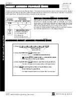
* User Program
User Program Option is enabled for Keypad 1 only, wherever it is connected. To enable
User Program Option for any user add 8 to the data entry Option (see example). Then,
User Programming can be performed only at Keypad 1 by a user code with user program
enabled.
Bypass Enable
Security Bypass--Bypass is enabled only with a security code.
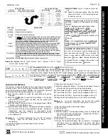
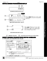
USER OPTIONS:
Area 1-4 options for 64 Us-
ers:
Select the desired options from the table
shown and enter in the remaining boxes
for each user code.
Example:
Program a code of “1234” for user 02,
with Area 1 options of “Arm/Disarm” and “User
Program”:
With “27” displayed in keypad window, press
R
,
0
2
(User 2),
R
1234
,
G
0
G
0
(User Code),
09
(User Area 1
options),
00
(User Area 2 Options), and
U
(save).
Notes:
(1) For
User Code
, press
G
0
for Blank Space; (2) For
User Options
, press
0
for Blank Space.
28
INTERIOR BYPASS FIRE/TBL SYS TBL CHIME
INTERIOR BYPASS FIRE/TBL SYS TBL CHIME
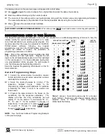
Quick Enroll Method
.
If a receiver is already installed in the panel, Napco transmitter
wireless points can be programmed automatically (“enrolled”)
using the following procedure.
NOTE:
The transmitter point will
be enrolled only if the signal strength is 3 or greater.
1. Enter the zone number to which the transmitter point will be
mapped.
2. Press the
B
button to enter the Enroll Mode. The red and
green LEDs on the keypad will flash and the window will
display as shown at left.
3. Open the loop of the point that is to be programmed (GEM-
TRANS2 or GEM-TRANS4 only).
4. Install the transmitter battery. The keypad will beep to indicate
that the point has been successfully enrolled. Multi-point
transmitters can be mapped to successive zones
simultaneously (Example 1) or to selected zones point by
point (Example 2).
Example 1.
A 4-point transmitter has the RF ID number
410078:1.
Map the first three points to Zones 11–13,
respectively.
1. Enter the Enroll mode as described in step 2 above.
2. Enter Zone “11”.
3. Open the loops of points 1, 2 and 3.
4. Install the transmitter battery. The keypad will beep 3 times to
indicate that three points have been programmed.
Transmitter 410078:1, point 1 will be mapped to Zone 11.
Transmitter 410078:1, point 2 will be mapped to Zone 12.
Transmitter 410078:1, point 3 will be mapped to Zone 13.
The keypad will now display Zone 13, the last zone enrolled.
Example 2.
A 2-point transmitter has the RF ID number
287613:1.
Map point 1 to Zone 6 and point 2 to Zone 9.
1. Enter the Enroll mode as described above.
2. Enter Zone “06”.
3. Open point-1 loop.
4. Install the battery. The keypad will beep once to indicate that
one point has been programmed. (Transmitter 287613:1,
point 1 will be mapped to Zone 6).
5. Enter Zone “09”.
6. Close point-1 loop and open point-2 loop.
7. Remove the transmitter battery, then re-install it. The keypad
will beep once to indicate that one point has been
programmed. (Transmitter 287613:1, point 2 is mapped to
Zone 9).
CHANGING OR CANCELING A CODE:
To change
any code, merely program over the existing code as
described above and press
U
to save. Similarly, to
cancel a code, blank out each number of the code
and press
U
to save.
Note:
Duplicate User Codes are
not allowed; therefore a duplicate Code entered in the
LCD Window will erase when
U
is pressed.
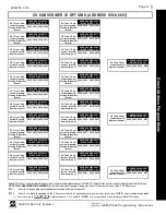
USER OPTIONS
USER CODE
(UP TO 6 DIGITS)
AREA 1
OPTIONS
AREA 2
OPTIONS
AREA 3
OPTIONS
AREA 4
OPTIONS
USER AREA OPTIONS
DATA ENTRIES
L
R
blank(•)
blank(•)
Disabled
blank(•)
1
Arm/Disarm
blank(•)
2
Arm Only
blank(•)
3
Service
blank(•)
4
Access
blank(•)
5
Ambush
blank(•)
Add 8
* User Program
4
blank(•)
Bypass Enable
OPTION
ENABLED