


Technical Manual
Stepper motor control
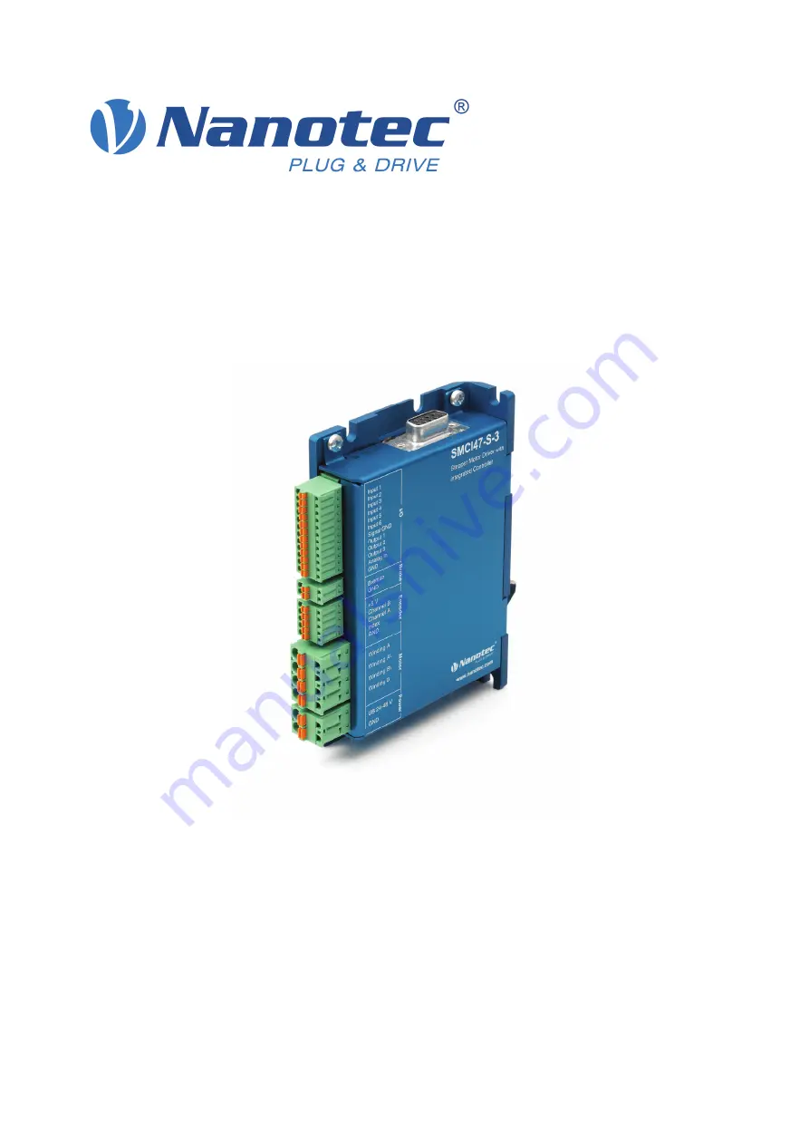
SMCI47-S
NANOTEC ELECTRONIC GmbH & Co. KG
Kapellenstraße 6
D-85622 Feldkirchen b. Munich, Germany
Tel. +49 (0)89-900 686-0
Fax +49 (0)89-900 686-50
[email protected]
Technical Manual
Stepper motor control
SMCI47-S
NANOTEC ELECTRONIC GmbH & Co. KG
Kapellenstraße 6
D-85622 Feldkirchen b. Munich, Germany
Tel. +49 (0)89-900 686-0
Fax +49 (0)89-900 686-50
[email protected]