


Technical Manual N5 (CANopen)
6 Operating modes
6.6.5 Use
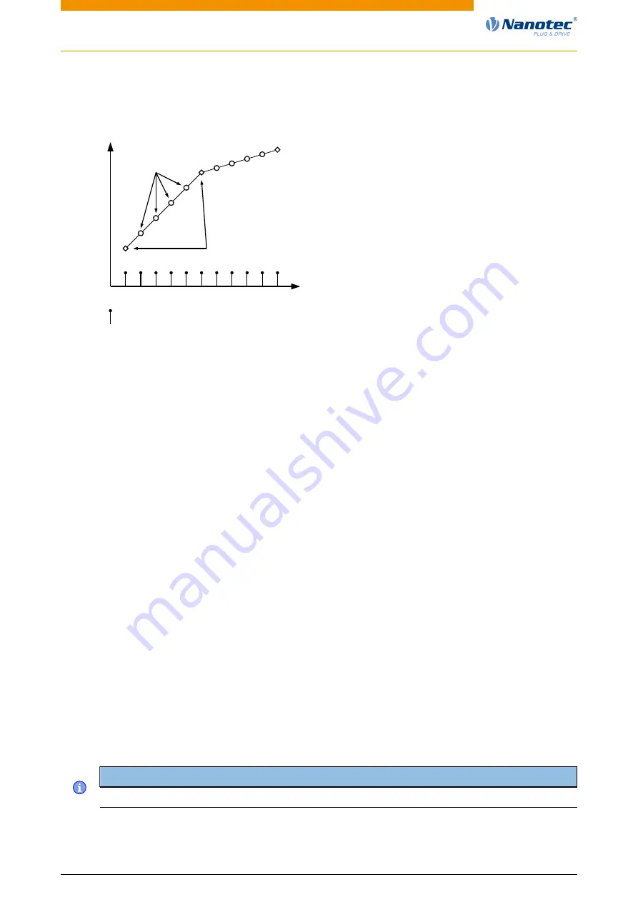
The controller follows a linearly interpolated path between the current position and the preset target
position. The (next) target position must be written in record 60C1
:01
h
.
Synchronisation
Data given
Own interpolated
data
t
po
si
tio
n
In the current implementation, only
•
linear interpolation
•
and a target position
are supported.
6.6.6 Setup
The following setup is necessary:
•
:01
h
: Time between two passed target positions in ms.
•
:06
h
: This object is to be set to "1" to be able to modify the target position in object 60C1
:01
h
.
•
To be able to turn the motor, the power state machine is to be set to the Operation enabled state
(see CiA 402 Power State Machine)
6.6.7 Operation
After setting up, the task of the higher-level controller is to write the target positions to object 60C1
:01
h
in time.
6.7 Cyclic Synchronous Position
6.7.1 Overview
Description
In this mode, the controller receives an absolute position preset via the fieldbus at fixed time intervals
(referred to in the following as a cycle). The controller then no longer calculates any ramps, but rather
only follows the presets.
The target position is transferred cyclically (via PDO). Bit 4 in the controlword does not need to be set
(unlike the Profile Position mode).
Note
The target is absolute and, thus, independent of how often it was sent per cycle.
Version: 2.0.1 / FIR-v1650
77


