background image

C

OMPONENTS


OF


THE

 S

YSTEM

17

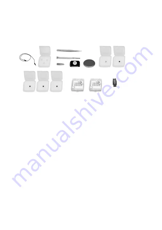
Contents of the Tool set

The contents of the Tool set depends on the available modules. It may con-
tain:

1. Ground cable

2. Protection feet

3. Cantilever tweezers: ACA 103

4. Screwdriver, 2.3 mm

5. Cantilever insertion tool (usually mounted in DropStop)

6. DropStop

7. Sample holder (with AFM Sample Stage)

8. a) AFM Large Scan Sample kit (option) with Grid: 10µm / 100nm, CD 

ROM piece


b) AFM High Resolution Sample Kit (option) with Grid: 660 nm, 
Graphite (HOPG) sample on sample support


c) AFM Basic Sample Kit (option, no longer available) with CD-ROM 
Sample, Microstructure sample

9. AFM Calibration Samples Kit (option) with Calibration grid: 10 µm/

100nm, Calibration grid: 660nm, Flatness sample

10. Set of 10 CONTR cantilevers (option)

11. Set of 10 NCLR cantilevers (option)

Contents of the AFM Tool set

12

7

6

8

9

10

1

2

3

4

5

11

Summary of Contents for easyScan 2 AFM

Page 1: ...Operating Instructions easyScan 2 AFM Version 1 6...

Page 2: ...NANOSURF AND THE NANOSURF LOGO ARE TRADEMARKS OF NANOSURF AG REGIS TERED AND OR OTHERWISE PROTECTED IN VARIOUS COUNTRIES MAY 07 BY NANOSURF AG SWITZERLAND PROD BT02089 V1 6R0...

Page 3: ...ep 1 Installation of hardware drivers 27 Step 2 Installation of the easyScan 2 software 33 Step 3 Installation of DirectX 9 34 Installing the software on different computers 34 Installing the drivers...

Page 4: ...ent plane 62 Measurement modes 65 Static Force 65 Dynamic Force 66 Phase Contrast 67 Phase measurement 68 Force Modulation 69 Spreading Resistance 70 The Signal Modules 72 Signal Module S 72 Signal Mo...

Page 5: ...tatic Force mode 97 The User Signal Editor 98 Dynamic Force mode 99 Phase Contrast mode 101 Force Modulation mode 102 Spreading Resistance mode 102 The Z Controller Panel 102 Cantilever types configur...

Page 6: ...ppearance of the 3D view 138 The Color Palette dialog 139 The Data Info panel 140 Quick Evaluation Tools 141 The Tool Results panel 141 The Tools bar 141 Storing measurements and further data processi...

Page 7: ...7...

Page 8: ...system The chapters Preparing for Measurement and A First Measurement should be read by all users because they contain useful instructions for everyday measurements The other chapters give more infor...

Page 9: ...e adds dynamic mode measurement capabilities for measuring delicate samples AFM Mode Extension Module adds phase contrast force modulation and current measurement capabilities AFM Video Module allows...

Page 10: ...axes Scan speed Up to 60ms line at 128 datapoints line Scan drive signals 10 V no high voltage Measurement channels 16bit A D converters up to seven signals depending on mode Scan area and data points...

Page 11: ...rol software Windows Scripting Host Visual Basic Script Java Script Remote control by COM compatible languages LabView MathLab Visual Basic Delphi C Operating system require ment Windows 2000 XP Vista...

Page 12: ...sync Additional signal modulation inputs X Axis Y Axis Z Axis Tip Voltage Excita tion Free connectors 2x Aux connection made on user request Modulation range 10 V Excitation 5 V Additional analog user...

Page 13: ...ew field Top 4x4 mm side 5x3 mm Sample illumination White LEDs sideways illumination adjust able brightness Manufacturers NanoSensors and NanoWorld Applied Nanostructures Static modes CONTR LFMR ZEILR...

Page 14: ...kHz 300kHz Dynamic frequency resolution 0 1Hz Additional imaging modes Phase Contrast Force Modulation Spread ing Resistance Additional spectroscopy modes Phase Distance Current Voltage Current Distan...

Page 15: ...ith your sys tem Some of modules listed in the delivery note are built into the Control ler Their presence is indicated by the status lights on the top surface of the Controller when it is turned on s...

Page 16: ...ext section 13 AFM Extended Sample Kit option not shown with set of 10 samples and description of experiments 14 AFM Sample Stage option 15 Micrometre Translation Stage option 16 User s Guide Translat...

Page 17: ...mple Stage 8 a AFM Large Scan Sample kit option with Grid 10 m 100nm CD ROM piece b AFM High Resolution Sample Kit option with Grid 660 nm Graphite HOPG sample on sample support c AFM Basic Sample Kit...

Page 18: ...ower is turned on The Probe Status light Indicates the status of the Z Feedback loop It can indicate the following statuses red The scanner is in its upper limit position This occurs when the tip samp...

Page 19: ...th which to do feedback The light intensity on the photodetector of the laser beam deflection system is too low Refer to section Probe Status light blinks red p 80 for more information The Scan Head l...

Page 20: ...when the Control ler has not been initialised yet The Module lights Indicate the modules that are built in into the Controller The module lights blink when the Controller has not been initialised yet...

Page 21: ...equipment clean Never touch the cantilever tips the cantilevers figure Contents of the AFM Tool set p 17 10 11 or the open part of the Scan head figure Cantilever deflection detection system p 38 Ensu...

Page 22: ...he cantilever with the top and side view lenses safe Older Scan heads may contain lasers with 850nm wavelength infrared light and lower optical power These lasers have laser class 1 which does not req...

Page 23: ...sing the screwdriver figure Contents of the AFM Tool set p 17 4 Connect the Scan head cable Components 6 to the Controller Compo nents 1 The scan head cable has a helix shape in order to isolate the S...

Page 24: ...the Break out cable Components 18 to the Signal Out connec tor on the Controller figure The easyScan 2 Controller In case of an upgrade the Controller must be sent in to your local Nanosurf distribut...

Page 25: ...ing until the Controller is initialised by starting the easyScan 2 software Storing the Instrument If you have to send in the instrument transport it or if you are not using it for some time please pa...

Page 26: ...lly look for the most un suit able driver on the Internet Turn on the computer and start Windows IMPORTANT Log on to your computer as an administrator Do not run any other program when you are install...

Page 27: ...ontroller now lights up on controllers with normal speed USB 1 1 The red USB power light on the controller starts to blink on controllers with high speed USB 2 0 If you have connected a high speed USB...

Page 28: ...Locate and install driver software recommended The Windows needs your permission to continue Dialog is now dis played Click the Continue button The following devices can be installed depending on the...

Page 29: ...o do to Select Browse my computer for driver software advanced A dialog called Browse for driver software on your computer now opens Select the path of the installation CD usually D Check the box Incl...

Page 30: ...installed Once the computer has rebooted Start the Setup program again by double clicking the installation CD in windows Explorer Click the Full Installation of Nanosurf easyScan 2 button The install...

Page 31: ...ing driver installation continue the setup nor mally When the setup is finished refer to section Driver problems p 66 Click OK in the Step 1 dialog Standard USB hub The operating system should first f...

Page 32: ...ler contains a Video Module The installation procedure depends on the version of the video module Video Module version 1 When the operating system finds the USB Device it asks what to do to install th...

Page 33: ...ew Hardware USB Device Found New Hardware USB EMP Audio Device Your New Hardware is now ready to use Wait until the ready to use message is displayed The drivers USB Compound device USB 2 0 A V Conver...

Page 34: ...ifferent computers You can install the easyScan 2 software on a different computer than the one that controls the measurement for example for running the microscope simulation or for off line data ana...

Page 35: ...to install the USB Video Adapter On some computers the detection and installation process may take some time 20 seconds or more please be patient Select Automatic installation During installation of t...

Page 36: ...t blinking and all other status lights turn off Start the easyScan 2 software on the control computer The main program window appears and all status lights are turned off Now a Message Controller Star...

Page 37: ...ith micrometer accuracy see figure Cantilever left Note though that this accuracy is only guaranteed when the cantilever and the mounting chip are absolutely clean Installation of the cantilever shoul...

Page 38: ...the cantilever in the Scan head WARNING As a consequence Always close the DropStop before inspecting or mounting a cantilever or the inspecting the alignment chip especially when using optical instru...

Page 39: ...ON Nothing should ever touch the cantilever especially the tip end The Cantilever Holder Spring see figure Cantilever deflection detection system is very delicate and should not be bent Always close t...

Page 40: ...gure Mounting the cantilever top left The Cantilever Holder Spring opens Use the Cantilever tweezers to remove the old cantilever from the instru ment figure Mounting the cantilever top right It is re...

Page 41: ...d the Probe Sta tus light on the easyScan 2 controller should now stop blinking red If this is not the case refer to Chapter Problems and Solutions p 77 Installing the sample Preparing the Sample The...

Page 42: ...ery pure in order to prevent the collection of impu rities on the surface when the solvent evaporates The sample should be cleaned several times to remove dissolved and redeposited contaminants if it...

Page 43: ...it consists either of silicon oxide hills on a silicon substrate with a period of 660 nm and an unspecified height The approximated height is 149 nm holes in a silicon oxide layer with a period of 66...

Page 44: ...th STM and AFM measurements In high resolution AFM measurements the atomic steps on the graphite surface can be seen Conductivity variations can be observed in spreading resistance mode size approx 5...

Page 45: ...n the sample holder figure Contents of the AFM Tool set p 17 7 Mounting a sample onto the sample holder The simplest way to mount the sample onto the sample holder Put a double sided adhesive tape on...

Page 46: ...to the ground con nector on the scan head using the ground cable figure Contents of the AFM Tool set p 17 1 CAUTION Avoid touching the cantilever when placing the sample holder under the Scan head If...

Page 47: ...ment or the cantilever In the simulation mode most functions of the real microscope are emulated The sample is replaced by a mathematical description of a surface When you start the easyScan 2 softwar...

Page 48: ...t or Calibration sample kit Preferably install the 10 m Calibration grid when using a 70 m or 110 m scan head and the 660 nm Calibration grid when using a 10 m scan head The measurement examples shown...

Page 49: ...the Esc key Type the corresponding character to change the unit prefix For example if the basic unit is Volts type m to change to millivolts type the space bar for volts type u for microvolts The sele...

Page 50: ...tip was driven into the sample and the Z scanner is fully retracted from the sample In this case the tip is probably damaged so you will have to start over again with installing a new tip green The ap...

Page 51: ...amount When the sample is reflective the mirror image of the cantilever should now be visible figure Side view of the cantilever after manual coarse approach When the sample is not reflective the sha...

Page 52: ...ar to its surface figure View of the cantilever after man ual approach right To use the top view If the Video Module is installed click in the Video panel If you do not have the Video Module use the t...

Page 53: ...Open the User interface dialog via the menu Options Config User Inter face Select the Standard level user interface mode Enable Display sweep chart in the Mode Properties section of the Oper ating mod...

Page 54: ...e Approach done appears when the approach has been completed Starting a measurement Now that the tip sample interaction defined by Set point is flowing between tip and sample you can start measuring C...

Page 55: ...ck and follow the instructions of the chapter Problems and Solu tions p 77 Selecting a measurement area You have prepared your measurement so that the scan line in the centre of the Line graph reprodu...

Page 56: ...e color map graph using the left mouse button Now the selection is enlarged to the whole display size You can abort the zoom function by clicking again The microscope will now start measuring a single...

Page 57: ...o your hard disk drive for example for loading it to Nanosurf Report Activate the measurement document by clicking in its window or by selecting it in the Windows menu Select the menu File Save as Sel...

Page 58: ...s Start menu Finishing Once you are done measuring Click to stop measuring Open the positioning window Click Retract the cantilever to a safe distance from the sample by clicking until the tip sample...

Page 59: ...FINISHING 59 IMPORTANT Always store the scan head with an old cantilever installed This will pre vent dust from gathering on the alignment chip and protect the alignment chip against damage...

Page 60: ...on Mechanical vibrations Measure the frequency of the vibrations to find out if the interference is due to mechanical vibrations These vibrations have a frequency that is a mul tiple of the rotation f...

Page 61: ...Infrared light sources can influence the deflection detection system This problem is especially severe when measuring in the Static Force mode Try the following in order to reduce the influence of inf...

Page 62: ...scanner are all parallel But in most cases the sample plane is tilted with respect to the XY plane of the scanner In this case the sample cross section in the X measurement direction has a certain slo...

Page 63: ...ce the automatic approach has been done because this will damage the tip During measurement the measurement plane should therefore be adjusted electronically using the parameters X Slope and Y Slope M...

Page 64: ...e angle tool section Measure Angle p 143 Use a single click to measure the angle relative to the X Axis Alter the value of X Slope in the Imaging options of the Imaging panel until the x axis of the s...

Page 65: ...n the Static Force mode the static deflection of the cantilever is used as the error signal for the Z Controller The Set point in Newton is calculated by multiplying the deflection with the spring con...

Page 66: ...vibration amplitude when it is excited with a sinusoidal signal with a frequency close to the cantilever s free resonance frequency When the cantilever tip comes close to the sample surface this vibra...

Page 67: ...mode can also be used to do Magnetic and Electrostatic Force Microscopy For more information on how to do Magnetic Force Microscopy refer to technical note TN00031 Magnetic Force Microscopy which can...

Page 68: ...ual as measured 90 sin actual reference with reference a reference phase that can be set by the user This has two important consequences The measured phase shift lies between 90 and 90 phase shifts ou...

Page 69: ...escription of how to operate the easyScan 2 AFM in force modula tion mode For a more detailed description of the parameters that you can set refer to section The Operating mode panel p 95 Proceed as f...

Page 70: ...de is an extension of the static force mode The static force acting on the cantilever is used to produce a topography image of the sample Simultaneously changes in the spreading resistance from the ca...

Page 71: ...ents but damage to the tip is likely IMPORTANT Standard CONTR cantilevers can not be used due to the surface oxide on the tip and the semiconducting contact between the tip and the sample EFM cantilev...

Page 72: ...s or Spectrum Analysers The signals are available on nine BNC connectors that are labelled with their signal names The signal names and their function are listed in the table Monitor Signals Signal na...

Page 73: ...or The pin out of this connector is shown in figure Voltage source connector Signal Module A The Signal Module A can be used for adding functionality to the easyScan 2 system in addition to the applic...

Page 74: ...ctroscopy measurements X Axis Input The Input voltage is added to the X Position command of the scanner Y Axis Input The Input voltage is added to the Y Position command of the scanner Z Axis Input Th...

Page 75: ...t Output section of the Operating mode panel This Section is only available in the Advanced Level User Interface Refer to section The User Signal Editor p 98 for a more detailed explanation User 1 Inp...

Page 76: ...e sample holder and the open part of the scanner clean If exposed to moisture high humidity corrosion will occur Clean the alignment chip by blowing away dust using dry oil free air or a soft brush Sc...

Page 77: ...easyScan 2 software is waiting for an answer from the controller Most likely the easyScan 2 controller is not connected to the mains power or not turned on In this case the status lights on the top of...

Page 78: ...ontroller In order to solve driver problems Check for driver updates on the Nanosurf Support web site Insert the installation CD for your instrument Log in on an administrator account Now open the dev...

Page 79: ...SOFTWARE AND DRIVER PROBLEMS 79 Device manager The drivers that may be installed on your system when your controller is connected to the computer...

Page 80: ...will now ask you were to look for the driver Tell windows to take the driver from the Installation CD AFM measurement problems Probe Status light blinks red This light will blink red when an insuffic...

Page 81: ...lines Change the cantilever if no improvement occurs after following these procedures Set point drift When part of the scan line in the Line graph is drawn red the tip has moved to its maximum or min...

Page 82: ...h information as possible such as A detailed description of what happened before the problem occurred For example When I click the approach button then quickly click abort the controller will not reac...

Page 83: ...is scanned very closely across the sample s surface The distance between the tip and the sample surface is so small that atomic range forces act between them In an AFM tip is attached to the end of a...

Page 84: ...urfaces is described The Nanosurf easyScan 2 AFM The easyScan 2 AFM is an AFM that can be used in both static and dynamic operating modes The AFM cantilever is a micro fabricated canti lever with an i...

Page 85: ...eeps the tip sample inter action constant by changing the tip height The output of this feedback loop thus corresponds to the local sample height An image of the surface is made by recording the sampl...

Page 86: ...AFM THEORY 86 Scanner coordinate system x y...

Page 87: ...orkspace In the following the workspace will be explained first then the actual functions of the software will be discussed in more detail The work space of the easyScan 2 software consists of the fol...

Page 88: ...the state of the instrument Operating windows Operating windows are used to perform specific operations with the micro scope These operations are controlled using specific panels and tool bars that a...

Page 89: ...the chapters Viewing measurement data p 134 and Storing measurements and further data processing p 151 Tool bars The tool bars can either be free floating windows figure below left or they can be doc...

Page 90: ...ey are associated with Most control panels dock to the Main window some dock to a task specific window The control panels give access to specific functions of the easyScan 2 AFM The control panels con...

Page 91: ...of panels to the side of its associated window or to the side of or below another panel that is already docked to this window drag its title bar to the desired position using the mouse cursor It is p...

Page 92: ...d The entered value is used on pressing the Enter or Return key or by activating another input The entered value is discarded on pressing the Esc key Type the corresponding character to change the uni...

Page 93: ...Controller Configuration Dialog section The Controller Configuration dialog p 110 Functions for storing and retrieving parameters are accessed via the menu File Parameters Save saves the parameters t...

Page 94: ...ace Mode Determines the number of parameters displayed in the various panels Easy level only those parameters that are absolutely necessary to do a measurement Standard level the commonly useful param...

Page 95: ...l is used to control the Z position To open the Operating mode panel click in the navigator The number of available modes depends on the Scan head and on the mod ules built into the easyScan 2 control...

Page 96: ...ating mode Easy Standard Advanced STM mode by default Operating mode Signals measured Static force Topography Cantilever deflection User Input 1 User Input 2 Dynamic force Topography Vibration amplitu...

Page 97: ...lever type The mounted cantilever type is used to auto matically determine the search range in the dynamic operating modes and to determine the correct calibration for the force set point in the stati...

Page 98: ...r Input Output section of the Operating Mode Panel The settings made in this dialog are stored in the Scan head calibration file Signal Name The name of the user signal This name is used throughout th...

Page 99: ...bration as a function of the excitation frequency When the search is successful the resonance curve contains a single peak at the free resonance frequency of the cantilever Afterward a second fine tun...

Page 100: ...ime an approach is started Clicking starts the automatic setting immediately Display sweep chart Standard Advanced When active the results of the vibration frequency search measurements are transferre...

Page 101: ...ibration Frequency in the Auto set mode The computer adjusts the Vibration frequency so that the cantilever vibration amplitude is Amplitude reduction percent smaller than the vibration amplitude at t...

Page 102: ...e the same as those for the Dynamic Force measure ment Spreading Resistance mode The operating mode panel for the Spreading Resistance mode is the same as that for Static Force operating mode The Z Co...

Page 103: ...may start to oscillate Thus the image will contain many measurement artifacts P Gain Standard Advanced The strength of the Z Controller reaction that is proportional to the error signal Increasing th...

Page 104: ...Position The Z Controller is not active the scanner remains in its current Z position Stop and Clear The Z Controller is not active the scanner is moved to the Ref Z Plane set in the Imaging Panel The...

Page 105: ...ror sig nal is the difference between the signal used for topography feedback and the current set point When the value of Error Range is reduced the reso lution of the error signal is increased Tip Pr...

Page 106: ...head requires the following cantilever properties The bottom of the sensor chip must have grooves that fit into the align ment chip The cantilever should have a nominal length of 225 m or more and a w...

Page 107: ...rce mode p 97 Resonance frequency The nominal resonance frequency of the cantilever type This frequency is used for the calculation of the automatic resonance frequency search range section Dynamic Fo...

Page 108: ...iguration by clicking Save As The scan head calibration editor In this window the calibration of all standard Inputs and Outputs can be configured individually along with some scanner The configuratio...

Page 109: ...d vice versa X Y Angle The angle between then the X and Y axis of the scanner hardware The software uses this value to correct the scan command signals such that the scan axes are orthogonal Rotation...

Page 110: ...scan axis calibration factor by a correction coefficient that has been determined by evaluating the measure ment of a calibration gird for example using SPIP Nanosurf Analysis Scan axis correction Th...

Page 111: ...t is connected to the USB port The number of this virtual serial port should be the same as the one shown in your the windows device manager dialog Video Signal The configuration of the easyScan 2 con...

Page 112: ...Check Scan Head In it the controller reports the current status information of the sensor or the approach platform If the Status light on the easyScan 2 controller is blinking red more detailed inform...

Page 113: ...og The About dialog displays various information that may be useful for diag nostics when you have problems with your instrument To open the About dialog Select the menu entry About The about dialog c...

Page 114: ...for getting more support When the microscope simulation is active the about dialog displays the serial number 000 00 000 is displayed The Nanosurf Web site and con tact address for information and so...

Page 115: ...positioning the tip with respect to the sample The Approach panel The Video panel with the Video Module The Video display with the Video Module Click in the Navigator to open the Positioning window T...

Page 116: ...released Decreases the tip sample distance at maximum speed until the button is released Increases the tip sample distance with the settings given in the Approach Options Starts the automatic approac...

Page 117: ...oach motor has stopped CAUTION Changing the Z Position when the tip is approached to the sample may cause tip damage when using high resolution scanners This can be due to play in the approach stage w...

Page 118: ...her hand the motor will not move when Appr speed is too small Max Withdraw Standard Advanced The maximum withdraw duration after clicking Max Approach Advanced The maximum approach duration after clic...

Page 119: ...e currently displayed image to a JPEG file that is selected using a Save file as dialog Video Options The Video Options section determines how the video signal is displayed There are separate sets of...

Page 120: ...Imaging panel with parameters that determine how the imaging is done The Imaging window also contains a number of charts that display the data from the ongoing measurement The imaging window can displ...

Page 121: ...top to the bottom If a measurement has been started using or the measurement stops automatically after one full image Selects an area that is to be measured in more detail The size and area of the ar...

Page 122: ...l numeri cally displays the change in position The change in the position is indicated by an arrow The start of the arrow is defined by the mouse cursor position where the left mouse button is clicked...

Page 123: ...image can then be captured immediately by clicking The measurement documents are labelled automatically with increasing numbers i e Image1 Image2 When leaving the program you will be asked if you want...

Page 124: ...hen the Check box is active the number of Lines is always equal to the number of Points Line In the easy and standard user interface mode the number of Lines is always equal to the number of Points Li...

Page 125: ...e centre position of the measured area can be changed by typing its posi tion as well as by using the Move tool in the imaging bar The zero position is the centre position of the scanner Image X Pos Y...

Page 126: ...rom top to bottom Measurement mode The X direction in which the data is acquired and stored Forward during forward scan only left to right in the image Backward during backward scan only right to left...

Page 127: ...l Tip Pos The Constant Height Imaging mode is mainly useful for EFM and MFM measurements For more information on how to do Magnetic Force Microscopy refer to technical note TN00031 Magnetic Force Micr...

Page 128: ...spectroscopic measurements are force distance curves in the AFM static force mode amplitude voltage curves in the AFM dynamic mode or current voltage curves with the STM The accuracy of the spectrosc...

Page 129: ...a number of charts that display the data from a previous imaging measurement and the data from the ongoing spectroscopic measurement The Spectroscopy window can display as many charts as the size of...

Page 130: ...h increasing numbers i e Image1 Image2 When leaving the program you will be asked if you want to save the unsaved measurement documents The Spectroscopy panel Modulation Easy Standard Advanced Modulat...

Page 131: ...nge the Modulated output from the Start to the End value Keep Z Controller active Advanced The Z Controller will continue to change the Z position so as to keep tip sample interaction constant This op...

Page 132: ...h tip sample interaction This is the default setting Abort modulation aborts the current modulation period and continues with the next modulation until the number of modu lations in Averages is reache...

Page 133: ...of the line in a spectroscopy measurement sequence X Pos to Y Pos to Easy Standard Advanced The XY coordinates of the end point of the line in a spectroscopy measurement sequence The from and to coord...

Page 134: ...o the data and the Color scale used to display the data The Color scale shows which measured signal level is mapped to which colour The colour mapping can be changed using the Color Palette dialog des...

Page 135: ...name Load loads a previously saved chart file IMPORTANT When you have not loaded another file Save will overwrite the original default chart arrangement file with the current settings The Chart bar Th...

Page 136: ...ppearance of the 3D view p 138 Shaded map creates an impression of the surface with lighting from the left This is achieved by combining the topography with its derivative Dual line graph both the For...

Page 137: ...nd on the operating mode the status of the User input section The Operating mode panel p 95 and the measurement mode section The Imaging panel p 123 Optimise Chart range Adjust the chart scale so that...

Page 138: ...earance of the 3D view Always click and hold the left mouse button on the 3D view chart while changing the 3D view The surface is reduced in feature complexity as long as the left mouse button is pres...

Page 139: ...reduction filters to remove unwanted measurement artefacts Set the light source direction to 90 parallel to the scan lines Click once or twice until no clipping of high features is visible or adjust...

Page 140: ...ies can be selected This palette is stored in a lut file that contains an ASCII table with RGB color values A dif ferent look up table can be selected by clicking the Browse button The Data Info panel...

Page 141: ...panel The Tool Results panel displays the results of the currently active tool The panel should automatically become visible when a tool is selected To make the panel visible click in the navigator Th...

Page 142: ...be moved by dragging the centre marker Measure Distance Starts measuring the distance between two parallel lines The measurement result is displayed in the Tool Results panel Distance is measured by d...

Page 143: ...wo meeting lines in the chart The first point of the first line is defined by the mouse cursor position where the left mouse button is clicked the second point by the position where the button is rele...

Page 144: ...e arrow points toward the for ward direction of the line The start of the arrow is defined by the mouse cursor position where the left mouse button is clicked the end of the arrow by the position wher...

Page 145: ...ned it can be resized by dragging one of its corners and moved to the desired position by dragging its centre point It is possible to define a rectangular i e non square area by pressing the Shift key...

Page 146: ...the Tool Results panel The parameters are calculated as follows The Roughness Average Sa The Valley depth Sv Sv lowest value 1 0 0 M 1 k N 1 l l k y x z MN Sa The Mean Value Sm The Peak Height Sp Sp h...

Page 147: ...he Measure Dis tance tool To determine the mean height difference select an area on each plateau and calculate the difference between their Sm values Correct Background Removes the effect of a wrong s...

Page 148: ...surement is shown in figure Correct scan line levels To use the tool draw a line through points that should have the same height in the same way as with the Measure Length tool After clicking the Exec...

Page 149: ...ered data is created Noise Filter The Noise filter removes high frequency noise from the image but applying the filter will also decrease the resolution of the image The Noise Filter is Correct scan l...

Page 150: ...Noise Filter button in the Tools bar A new measurement docu ment with the filtered data is created Tip Filters are especially useful for improving the appearance of 3D views Applying filters may chang...

Page 151: ...ys Save and Save as Save a measurement document in Nanosurf image data format file exten sion nid The same dialog is opened using the menu File Save and File Save as Export Current Chart as Current do...

Page 152: ...n be used for detailed data analysis by various mathematical software packages such as MathLab or plotted by GnuPlot If Line graph is selected as Display in the Chart bar only the visualised lines wil...

Page 153: ...Nanosurf Report software package offers a powerful and extensive set of analysis functions Complex analyses can be created interactively and then displayed and printed in visually appealing reports T...

Page 154: ...fferent number of measurement chan nels than the template uses the results may not be correct The Report generator configuration dialog is used to configure the behav iour of the Navigator Icon and th...

Page 155: ...ig Report Navigation bar Determines what happens when the icon is clicked The check box determines whether the active measurement is evaluated using a template The Browse button is used to select the...

Page 156: ...instructions on the Access code certificate delivered with the instru ment For more information about the automating measurement tasks and the available script commands refer to the Programmers Manua...

Page 157: ...he easyScan 2 software has an simple integrated Script Editor that allows editing running loading and saving scripts The can be used in parallel with other application windows so you can work with oth...

Page 158: ...ASKS 158 The Script Configuration Dialog The Script Configuration Dialog allows you to set the search path for the scripts that are displayed in the Script menu The dialog is accessed via the menu ent...

Page 159: ...THE SCRIPT CONFIGURATION DIALOG 159 This page was intentionally left blank...

Page 160: ...AUTOMATING MEASUREMENT TASKS 160 This page was intentionally left blank...

Page 161: ...THE SCRIPT CONFIGURATION DIALOG 161 This page was intentionally left blank...

Page 162: ...ose Export 151 Open 151 Parameters 93 Print 153 Print preview 153 Print Setup Save 151 Save as 151 Workspace 91 Options Check Scan Head 112 Config Access Codes 112 Config Cantilever Types 106 Config C...

Page 163: ...163 Window Operating windows Imaging 120 Positioning 115 Report 153 Spectroscopy 128...

Page 164: ......

Reviews: