


FP0 Hardware
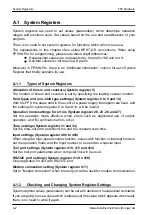
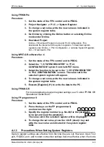
System Registers
A-4
Matsushita Electric Works (Europe) AG
is changed from PROG. to RUN. With regard to the modem connection setting, when
the power is turned on or when the mode is changed from PROG. to RUN, the controller
sends a command to the modem which enables it for reception.
When the initialized operation is performed, all set system register values (parameters)
will be initialized.
A.1.4
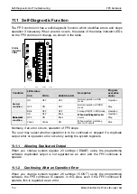
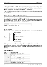
Content of System Register Settings
Setting the timers and counters (System register 5)
By indicating the counter start number, the timer and counter are split into two areas.
The timer and counter together total 144 points, and the default value for the split is 100.
Thus the point allotment is as shown in the table below.
Timer
100 points (No. 0 to No. 99)
Counter
44 points (No. 100 to No. 143)
Setting example
To increase the number of timers to 120, change the value of system register 5 to K120.
Set
value: n
Timer
Counter
MIN (0): All counter
MAX (144): All timer
Set value < n
Counter size increases
Set value > n
Timer size increases
0
144
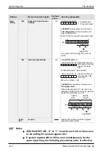
Hold types and non–hold type settings (System registers 6 to 8 and 14)
With the FP0, the areas held in the event of a power supply interruption are fixed at the
areas shown in the table below, and the settings for system registers 6 to 8 and 14, will
be invalid.
C10/C14/C16 series
Timer
Non-hold type: All points
Counter
Non-hold type: From the set value to C139
Hold type: 4 points (elapsed values)
C140 to C143
Internal relay
Non-hold type: 976 points (R0 to R60F)
61 words (WR0 to WR60)
Hold type:
32 points (R610 to R62F)
2 words (WR61 to WR62)
Data register
Non-hold type: 1652 words (DT0 to DT1651)
Hold type: 8 words (DT1652 to DT1659)
Summary of Contents for FP Series
Page 12: ...Chapter 1 Overview...
Page 21: ...FP0 Hardware Overview 1 10 Matsushita Electric Works Europe AG...
Page 22: ...Chapter 2 Control Units...
Page 44: ...Chapter 3 Expansion I O Units...
Page 67: ...FP0 Hardware Expansion I O Units 3 24 Matsushita Electric Works Europe AG...
Page 68: ...Chapter 4 Analog I O Unit...
Page 87: ...FP0 Hardware Analog I O Unit 4 20 Matsushita Electric Works Europe AG...
Page 88: ...Chapter 5 FP0 I O Link Unit MEWNET F...
Page 102: ...Chapter 6 Power Supply Unit...
Page 105: ...FP0 Hardware Power Supply Unit 6 4 Matsushita Electric Works Europe AG...
Page 106: ...Chapter 7 I O Allocation...
Page 112: ...Chapter 8 Installation...
Page 122: ...Chapter 9 Wiring...
Page 139: ...FP0 Hardware Wiring 9 18 Matsushita Electric Works Europe AG...
Page 140: ...Chapter 10 Trial Operation...
Page 143: ...FP0 Hardware Trial Operation 10 4 Matsushita Electric Works Europe AG...
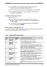
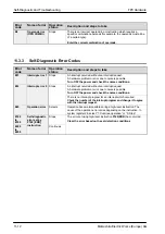
Page 144: ...Chapter 11 Self Diagnostic and Troubleshooting...
Page 156: ...Appendix A System Registers...
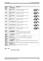
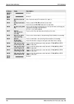
Page 170: ...Appendix B Special Internal Relays...
Page 174: ...Appendix C Special Data Registers...
Page 183: ...FP0 Hardware Special Data Registers C 10 Matsushita Electric Works Europe AG...
Page 184: ...Appendix D Dimensions...
Page 195: ...FP0 Hardware Dimensions D 12 Matsushita Electric Works Europe AG...