background image

12

REAR PANEL

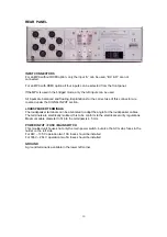
INPUT CONNECTORS

For an MPA without RCMI option, only the input “A” can be used, “B,C & D” are not
connected.

For an MPA with RCMI option all four inputs can be selected from the front panel.

If the MPA is used in the bridged mode, only the left inputs can be used.

All inputs are balanced and floating. Explanations for the correct use of this connector are
covered under the SIGNAL INPUT section.

LOUDSPEAKER TERMINALS

The loudspeaker terminals can be orientated to adapt the angle for the loudspeaker cables.
The terminals are electrically isolated, this to be conform to the electrical security regulations.
Maximum cable diameter to fit into the terminals is 4.5 mm.

POWER INPUT / FUSE / MAIN SWITCH

This moulded unit houses not only the main power switch, but also the AC mains fuses in the
holder on the left side.
For 94V – 135 V operation two 10A


fuses should be installed

For 186V – 264 V operation two 5A fuses should be installed

GROUND

A ground terminal is available in the lower left corner.

Summary of Contents for MPA

Page 1: ...1 Nagra MPA Amplifier Owner s Handbook Nagravision S A Kudelski Group CH 1033 Cheseaux Switzerland All rights reserved November 2002 KSA P N 2055 005 151 ...

Page 2: ...al 8 Parallel 8 Stereo 8 CONNECTING THE AC MAINS POWER 8 SWITCHING ON 9 SWITCHING OFF 9 WITHOUT RCMI OPTION 10 WITH RCMI OPTION 10 REAR PANEL 12 INPUT CONNECTORS 12 LOUDSPEAKER TERMINALS 12 POWER INPUT FUSE MAIN SWITCH 12 GROUND 12 REMOTE CONTROL 13 Buttons 1 to 6 13 Buttons A to D 13 ON OFF 13 Mute 13 Up Down arrow keys 13 Left Right arrow keys 13 Center button 13 Battery installation 14 Product ...

Page 3: ...u have any questions regarding the installation or operation of your MPA amplifier please contact your dealer NAGRAVISION S A DECLINES ALL RESPONSIBILITY IN THE EVENT OF AN ACCIDENT CAUSED BY THE NON OBSERVANCE OF THESE INSTRUCTIONS OR ANY OTHER FORM OF USER NEGLIGENCE SAFETY In the event that the case of the MPA is opened the AC mains power must be disconnected However it should be remembered tha...

Page 4: ...eight costs as well as customs duty and other possible charges are at the customer s expense Our warranty remains valid in the event of emergency repairs or modification being made by the user However we reserve the right to invoice the customer for any damage caused by an unqualified person or a false manoeuvre or operation by the user We decline any responsibility for any and all damages resulti...

Page 5: ...ank you for being our customer and enjoy your new Nagra MPA amplifier ABOUT YOUR MPA The NAGRA MPA amplification system consists of a stereo block amplifier of the finest quality which is designed for vertically or horizontally position The MPA is designed and hand built entirely in Switzerland by NAGRA engineers using components of the highest possible quality from around the world Fully symmetri...

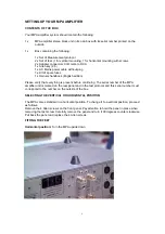
Page 6: ...ish edition Please verify that everything is present before continuing The serial number of the MPA amplifier unit is marked on the rear panel and in the test protocol and this serial number must correspond to the number on the outside of the box SELECTING THE VERTICAL OR HORIZONTAL POSITION The MPA comes standard in a horizontal position To change it to a vertical position proceed as follows Remo...

Page 7: ...rovided CONNECTING THE MPA TO THE SOURCE PREAMPLIFIER Connect the source preamplifier to the 3 pole XLR balanced input connectors left and right channel A if no RCMI option on the rear panel of the MPA If necessary use the XLR RCA adapter connector supplied to connect an unbalanced RCA lead to the XLR connector CONNECTING THE LOUDSPEAKERS On the rear of the MPA stereo block there are two pairs of ...

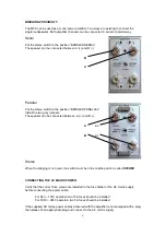
Page 8: ...mpers The speaker can be connected between A and B A or B or Stereo When the bridging is not used the switch must be in the middle position called STEREO CONNECTING THE AC MAINS POWER Verify that the correct fuse values are installed in the fuse holder of the AC mains supply before connecting the power cable For 94V 135V operation two 10A fuses should be installed For 186V 264V operation two 5A fu...

Page 9: ... ATTENTION When switching on the MPA an electro mechanical noise is emitted This is due to the start of the two PFC s inside the machine SWITCHING OFF Always switch OFF the MPA by the front OFF button Switching OFF by the main switch on the back panel will created a loud pop in the loudspeakers and the internal capacitors will stay charged ...

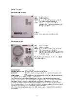
Page 10: ...ferent line inputs BALANCE Permits to adjust in a range of 6 dB the output level between left right INPUT LEVEL The external scale is calibrated from 50 dB to 0 dB and indicates the absolute attenuation obtained with the potentiometer The internal scale fat scale is calibrated from 12 dB to 0 dB and shows the input level relative to 1 V when the modulometer indicates 0 dB The same fat scale area a...

Page 11: ... has a ballistic identical to that of a modulometer It shows the peak value of the signal The upper scale shows the input level up to 3 dB The lower scale shows the output power up to 250 W 0 dB indication corresponds to 200 W if the speakers are 8 Ohm ...

Page 12: ...tion LOUDSPEAKER TERMINALS The loudspeaker terminals can be orientated to adapt the angle for the loudspeaker cables The terminals are electrically isolated this to be conform to the electrical security regulations Maximum cable diameter to fit into the terminals is 4 5 mm POWER INPUT FUSE MAIN SWITCH This moulded unit houses not only the main power switch but also the AC mains fuses in the holder...

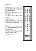
Page 13: ...n turns green and the backlight of the modulometer switches on When the OFF button is pressed the MPA goes back to standby mode and the backlight of the modulometer switches off If the MPA was not muted before switching off the led stays green if the MPA was muted before switching off the led stays red In the OFF status only the remote receiver stays powered Mute Pressing once on the mute button t...

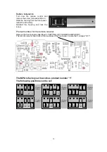
Page 14: ...mote receiver Remove the front panel as described in SETTING UP YOUR MPA AMPLIFIER The remote receiver board sits at the backside of the front panel Locate the 5 jumpers ST1 The MPA is factory set to work as product number 1 The following positions can be set 1 2 3 4 5 Product number 5 1 2 3 4 5 Product number 1 1 2 3 4 5 Product number 2 1 2 3 4 5 Product number 3 1 2 3 4 5 Product number 4 1 2 3...

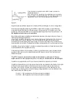
Page 15: ...f obtaining the constant voltage needed to power a piece of electronic equipment The AC mains feed a power transformer a diode bridge rectifies the voltage of the secondary which is then filtered by a capacitor which gets larger as the quality of the equipment s circuits increases Figure 1 The more modern preferable way to obtain a continuous voltage is first to rectify the AC supply directly and ...

Page 16: ... It won t be long before they overheat and make doubtful connections Perhaps the insulation will degrade and in some cases catch fire In addition these highly spiked currents are wonderful generators of nasty harmonics that could well disturb other equipment nearby In the USA and other 110V countries in order to avoid these risks users of power thirsty equipment often are forced to install dedicat...

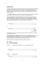
Page 17: ... the signal is then placed on pin 2 and the screen to the bridged 1 3 Adapters which do this are readily available on the market Neutrik for example and such connectors have a female RCA connector on one end and a male XLR on the other end or Neutrik Adapter If hum difficulties arise please refer to the manual of the PL P for instructions on AC Mains supply wiring possibilities If hum still persis...

Page 18: ...e the MPA in any way PROTECTIONS Static limitation on the output stage starts at a current drain of 17 App Peak to Peak Dynamic limitation on the output stage starts at a current drain of 25 App after approximately 150 ms If during a period of minimum 1 second a DC current of more than 200 mV appears at the output the output stages are powered off and the protection led switches on This happens al...

Page 19: ...19 Attention Do never install the MPA without feet In this case the cooling will not work correctly and the amplifier could be damaged due to high internal temperature ...

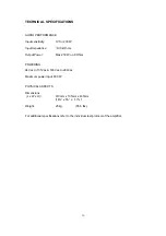
Page 20: ...ce 100 kOhms Output Power Max 250 W on 8 Ohms POWERING 94Vac to 135Vac 186Vac to 264Vac Maximum power input 830 W PHYSICAL ASPECTS Dimensions L x W x H 410mm x 135mm x 435mm 16 x 5 x 17 Weight 25 kg 55 5 lbs For additional specifications refer to the individual test protocol of the amplifier ...

Page 21: ...N 55022 Cl B Disturbance voltage on mains terminal EN 55022 Cl B Immunity to electromagnetic fields EN 61000 4 3 Immunité aux décharges électrostatiques EN 61000 4 2 Immunity to electrostatic discharges EN 61000 4 2 Cheseaux 4 ème trimestre 2001 Cheseaux 4 rd quarter 2001 NAGRA KUDELSKI are registered trademarks property of KUDELSKI S A CHESEAUX SWITZERLAND All specifications contained in this pub...

Reviews: