background image

10

IMPORTANT NOTES

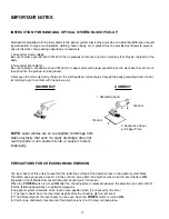
INSTRUCTION FOR HANDLING OPTICAL SYSTEM BLOCK PICK-UP

Electrostatic breakdown of the laser diode in the optical system block may occur due to a potential difference caused
by electrostatic charge accumulated on clothing, human body, etc. A ground must be provided as follows to prevent
any electrostatic charge during unpacking or repair work.

1. Ground for Human Body
Be sure to wear a ground band (1M ohm) that is properly to remove any static electricity that may be charged on the
body.

2. Ground for Work Bench
Be sure to place a conductive sheet (1M ohm) or copper plate with proper grounding on the work bench or other sur-
face on which the pick-up is to be placed.

3. Because the static electricity charge on the clothing does not discharge through the body grounding band, do not
let clothing to get in contact with the pick-up unit. 

PRECAUTIONS FOR CHECKING BEAM EMISSION

The laser beam of this unit is focused on the reflecting surface of the objective lens in the optical system block.
Therefore, keep your eyes at least 12 inches (30 cm) away from the objective lens when the laser diode is 

ON

.

(Operation Check Method for Laser Diode and Focus Search Function.)
When the 

POWER

switch is turned 

ON

after the chucking plate is removed, observe the objective lens and confirm

that the following operations are performed properly.
(The optical system should be at the lead-in area position when it is checked at this time.)
(1) The laser should be at the innermost position after the chucking plate is removed.
(2) The diffused light of the laser beam can be seen when the 

POWER

switch is turned 

ON

.

(3) Vertical (up and down) movement of the objective lens (2 or 3 times) will take place.

INCORRECT

CORRECT

NOTE

: Laser diodes are so susceptible to damage from

static electricity that even if a static discharge does not
ruin the diode, it can shorten its life or cause it to work
improperly.

1.Grounding band

1M ohm

1M ohm

2.Conductive Sheet
or Copper Plate

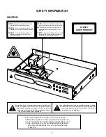
Summary of Contents for C521i

Page 1: ...NAD C 521i COMPACT DISC PLAYER C 521iCOMPACT DISC PLAYER SERVICE MANUAL...

Page 2: ...ALUKITUSOHITETTAESSAOLET ALTTIINAN KTM T NT LASERS TEILYLLE L KAISO S TEESEEN VORSICT UNSICHTBARELASERSTRAHLUNG TRITTAUS WENN DECKELGE FFNETUNDWENNSICHERHEITSVERRIEGELUNG BERBR CKTIST NICHTDEMSTRAHLAU...

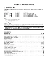
Page 3: ...the customer make leakage current or resistance measurements to determine that exposed parts are acceptably insulated from the supply circuit Parts marked with the symbol are critical with regard to...

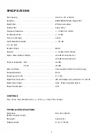
Page 4: ...Ratio A Weight 106 dB De Emphasis on 106 dB De Emphasis off Channel Separation 1kHz 90 dB 10 kHz 80 dB Wow and Flutter Unmeasurable Quartz Crystal Accuracy Output Impedance 200 Output Level at 0 dB 2...

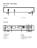
Page 5: ...TAL OUT 3 AC LINE CORD 1 POWER ON OFF 2 DISC DRAWER 3 DISPLAY 4 OPEN 5 PLAY PAUSE 6 TIME 7 STOP 8 REPEAT 9 RANDOM 10 SCAN Back Forward 11 SKIP Back Forward 12 STANDBY LED i 1 i REAR PANEL FRONT PANEL...

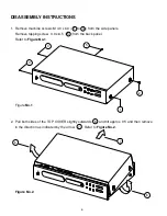
Page 6: ...ide panels Remove tapping screw 3 0 x 8 5 5 from the back panel Refer to Figure No 1 Figure No 1 2 Pull both sides of the TOP COVER slightly outwards 6 and tilt approx 35 and then remove in the direct...

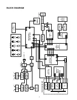
Page 7: ...RFDC FE SE Q104 Q107 MOTOR DRIVER U201 BA6392 FOCUS TRACKING MOTOR DRIVER LOADING MOTOR LOADING MOTOR LIMIT SWITCH SPINDLE MOTOR SLED MOTOR PU IN LIMIT SWITCH PICK UP DISC M113 REMOTE SENSOR CD MECHAN...

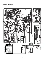
Page 8: ...J403 J406 J407 J402 J404 J401 1723 006A 0000 8V 0V 0V 8V 15V 0V 15V ISSUE B M120C M505B M301 LIVE NEUTRAL M500A M102 16PIN M105 6PIN M505A CD MECHANISM TRANSFORMER BOARD DISPLAY BOARD KEY BOARD LIVE B...

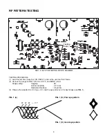
Page 9: ...d set the unit into PLAY mode 2 Connect the scope to R227 Pin 15 of U101 and DGND J144 Scope setting Coupling AC Vertical sensitivity 0 2 V div Horizontal time base 0 5 S div 3 Observe the waveform is...

Page 10: ...BEAM EMISSION The laser beam of this unit is focused on the reflecting surface of the objective lens in the optical system block Therefore keep your eyes at least 12 inches 30 cm away from the objecti...

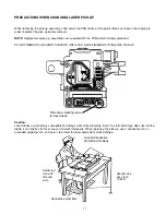
Page 11: ...NTIL YOU HAVE FINISHED FITTING THE PICK UP Caution Laser diodes are extremely susceptible to damage from static electricity Even if a static discharge does not ruin the diode it can shorten its life o...

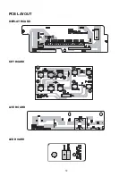
Page 12: ...12 PCB LAYOUT DISPLAY BOARD KEY BOARD LIVE BOARD LED BOARD...

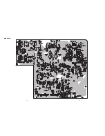
Page 13: ...14 13 MAIN BOARD...

Page 14: ...1K R207 1K R208 1K R209 1K R210 1K R211 1K R212 100K R213 10K R214 8K2 R215 4R7 R216 0R R217 1K R218 15K R219 15K R220 100K R222 0R R223 33K R224 10K R225 100K R226 1M R227 100 R228 3K3 R229 3K3 R230...

Page 15: ...1 2X DISCO DI SW R327 4K7 R326 4K7 R325 4K7 R323 4K7 R322 4K7 R321 4K7 SQSO SENS C301 33p C302 33p C303 0 01u 1 2 3 Q308 8050 R329 4K7 R328 4K7 D303 IN4148 R338 10K R339 100K C308 10u 6 3V VCC C307 47...

Page 16: ...23 10u 6 3V C322 104K A 5V D 5V 2 3 1 U306A 5532 6 5 7 U306B 5532 8 4 U305C 5532 DGND R378 4K7 R382 4K7 R414 100K A 12V C375 22u 25V C377 224K R355 3K3 R359 6K8 C352 330p R363 1K5 R367 2K2 R371 2K2 C3...

Page 17: ...0R C522 100u 16V ELD1 C502 104K C503 104K D501 1N4001 D502 1N4001 C506 2200u 25V Vin GND Vout 1 2 3 U502 7812 C504 104K D504 1N4001 D503 1N4001 C505 104K C507 2200u 25V C526 104K C512 1000u 16V C513 1...

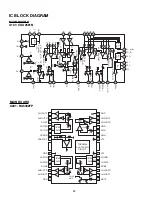
Page 18: ...VC DVcc DVcc DVcc gm gm VC VC VOFST DVC DVC VC Vcc APC OFF Hi Z RW ROM H L Vcc 22 IC BLOCK DIAGRAM MAIN BOARD U101 CXA2581N 1 CH1OUTF 28 GND 2 F INTER FACE REV FWD R CH1OUTR 27 CH4OUTF 3 RCIN1 26 CH4O...

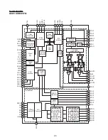
Page 19: ...ENERATOR PWM GENERATOR OPAmp Analog SW A D Converter Asymmtery Corrector Digital PLL Digital CLV CPU Interface XTSL XUGF GFS EMPH WFCK C2PO LRCK PCMD BCK SYSM TES1 TEST XRST RMUT LMUT XTAI XTAO AOUT1...

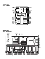
Page 20: ...display RAM 16 bytes LCD drive control circuit A 25 Reset input RESET 71 5V Vcc 0V Vss 30 78 VL3 77 COM0 76 COM1 75 COM2 74 COM3 70 SEG0 69 SEG1 68 SEG2 67 SEG3 66 SEG4 65 SEG5 64 SEG6 63 SEG7 62 SEG8...

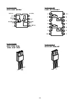
Page 21: ...8 MAIN BOARD U403 TC74HC00AP V0 GND V1 MAIN BOARD U503 UPC79M12HF AMPLIFIER 1 OUTPUT INVERTING INPUT NON INVERTING INPUT V AMPLIFIER 2 V OUTPUT INVERTING INPUT NON INVERTING INPUT 1 2 3 4 8 7 6 5 MAI...

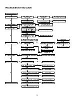
Page 22: ...CIRCUIT Q301 Q302 Q303 Q304 LINE OUT PLUG OR PATTERNS DEFECTIVE MUTE CIRCUIT DEFECTIVE IC U301 DEFECTIVE M101 SWITCH DEFECTIVE OR PATTERN AND CONNECTOR OPEN IS OSCILLATOR CIRCUIT OSCILLATING POWER SU...

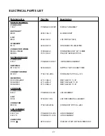
Page 23: ...3538 0 SWITCH TACT SKHHBY 7MM CONNECTOR WIRE M120C 7705 1120 2204 CONN ASSY 5P P2 5 L 120 RESISTORS R301 R306 R307 4711 102A 2 RMF 1 8W 1K 1 AT R302 R303 4711 622A 2 RMF 1 8W 6 2K 1 AT R304 R305 4711...

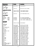
Page 24: ...FC CC 50V 0 1 F 10 AT 3 5x2 C209 C223 153F 152J 5 JM CM 50V 1500PF 5 RL 5 8x7 C210 C213 C217 C222 150F 104K 2 FC CC 50V 0 1 F 10 AT 3 5x2 C211 C212 15CH 270J 5 GG CTC 0 60 27pF 5 RL 4x4 C214 C215 150F...

Page 25: ...9 CE 16V 1000 F 20 RL 10x20 C518 157E 107M 5 KW CE 25V 100 F 20 RL 6x12 C521 150F 104K 2 FC CC 50V 0 1 F 10 AT 3 5x2 C522 157D 107M 5 IU CE 16V 100 F 20 RL 5x11 C523 157F 225M 5 IU CE 50V 2 2 F 20 RL...

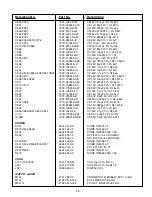
Page 26: ...R101 4701 100J C RCF 1 8W 10R 5 ATS R103 R104 4701 203J C RCF 1 8W 20K 5 ATS R105 R110 4701 302J 2 RCF 1 8W 3K 5 AT R106 4701 154J C RCF 1 8W 150K 5 ATS R107 4701 104J C RCF 1 8W 100K 5 ATS R108 4701...

Page 27: ...C RCF 1 8W 7 5K 5 ATS R412 4701 472J C RCF 1 8W 4 7K 5 ATS R413 R416 4701 473J C RCF 1 8W 47K 5 ATS R414 4701 104J C RCF 1 8W 100K 5 ATS R501 4711 273A C RMF 1 8W 27K 1 ATS R502 4701 183J C RCF 1 8W...

Page 28: ...32 MECHANISM EXPLODED VIEW 27 11 3 15 28 29 22 10 1 9 24 x2 21 x4 x2 x4 23 30 31 x2 8 26 26 5 12 17 16 6 25 x2 x2 14 32 20 13 25 19 18 x2 2 7 4 WSL 2130CCM...

Page 29: ...9014 0 Optical Pickup Unit 1 16 4102 9015 0 Loading PWB 1 17 4102 9016 0 Motor RF 500TB 14415 1 18 4102 9017 0 Leaf Switch 1 19 4102 9018 0 Connector pin 5P 1 20 4102 9019 0 Magnet 1 21 4102 9020 0 I...

Page 30: ...34 EXPLODED VIEW...

Page 31: ...HER 4 0202 2954 3008 3000 T3X8MM SELF TAPPING 12 0205 2954 3008 0000 TAPPING 3X8MM B TITE YEL ZN 17 0208 2842 3367 0 METAL WASHER ID 3 3 OD 6 7 4 0209 2900 4010 3030 PH W WASHER M4X10 BL ZN 2 0211 290...

Page 32: ...S 2 40 2103 7302 1 RCA CABLE 1 41 8912 0005 0 REMOTE CONTROL HANDDSET 1 42 1497 1302 0 REMOTE CONTROL POLYBAG 1 43 4301 4165 0 INSTRUCTION MANUAL 1 44 1497 1062 0 MANUAL POLYBAG 1 45 1435 8300 0 2 CAR...

Page 33: ...SERVICE MANUAL NAD 2002 C 521i COMPACT DISC PLAYER NAD ELECTRONICS INTERNATIONAL TORONTO...

Reviews: