2.3 Connected signals
2-20
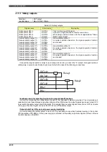
2.3.5 Monitor inputs
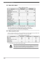
Electrical
specifications
Rating DC26V, 5mA
Connect the dry contacts.
To prevent defective contact and other problems, use a device which can turn on and off
the very small load specified above.
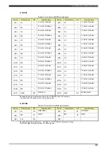
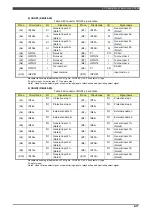
Table 2-16 Monitor inputs
Signal name
Circuit
code
Description
Electrical
specifications
Power shutoff
instruction
GPIN4
This signal is to shut off the motor power
On: Motor power supplied
Off: Motor power cut off
Photo-coupler input
Rating DC26V
Input current 5mA
LS release switch
GPIN7
This signal is to release the over travel switch.
When the limit switch error or operating range
monitoring error or angle monitoring error was
occurred, this signal will used to operate the robot
manually in TEACH mode.
This switch (momentary switch) must be operated
only by well-trained, dedicated maintenance staff.
Photo-coupler input
Rating DC26V
Input current 5mA
System OK
GPIN5
This signal is from the robot controller.
This signal is always ON while the controller
operates normally
Photo-coupler input
Rating DC26V
Input current 5mA
TEACH mode
GPIN3
This signal is for selecting the mode in which the
teaching operation via teach pendant is performed.
Connected to the selector SW on the operation
panel.
Photo-coupler input
Rating DC26V
Input current 5mA
PLAYBACK mode
GPIN2
This signal is for selecting the mode in which the
playback operation is performed.
Connected to the selector SW on the operation
panel.
Photo-coupler input
Rating DC26V
Input current 5mA
Tool number 1
GPIN13
Signal that inputs tool number from PLC.
To use the tool number monitoring function, it is
necessary to enable the "Tool watch" in the
parameter setting screen.
Photo-coupler input
Rating DC26V
Input current 5mA
Tool number 2
GPIN14
Signal that inputs tool number from PLC.
To use the tool number monitoring function, it is
necessary to enable the "Tool watch" in the
parameter setting screen.
Photo-coupler input
Rating DC26V
Input current 5mA
Tool number 3
GPIN15
Signal that inputs tool number from PLC.
To use the tool number monitoring function, it is
necessary to enable the "Tool watch" in the
parameter setting screen.
Photo-coupler input
Rating DC26V
Input current 5mA
Tool number 4
GPIN16
Signal that inputs tool number from PLC.
To use the tool number monitoring function, it is
necessary to enable the "Tool watch" in the
parameter setting screen.
Photo-coupler input
Rating DC26V
Input current 5mA
Summary of Contents for RMU20-20
Page 2: ......
Page 6: ...Contents 4 ...
Page 8: ......
Page 26: ...1 4 EC DECLARATION OF CONFORMITY FOR MACHINERY 1 18 NOTE ...
Page 68: ...2 9 Enabling RMU 2 40 NOTE ...
Page 70: ......
Page 100: ...3 4 Setting when a slider unit is used 3 30 NOTE ...
Page 102: ......
Page 138: ...4 4Approval 4 36 8 Approval is completed The following screen will be displayed ...
Page 144: ......
Page 154: ...5 4Trouble shooting 5 10 NOTE ...
Page 156: ......
Page 166: ...6 4Trouble shooting 6 10 NOTE ...
Page 168: ......
Page 189: ......


