5.1 Outline of the EtherNet/IP safety network function
5-1
5.1
Outline of the EtherNet/IP safety network function
This section describes the setting procedures for RMU20-30 that supports EtherNet/IP safety network function.
This function is available only in the RMU20-30.
Using the RMU20-30, it is possible to use the safety network based on EtherNet/IP Safety.
Using the safety network, for example, it is possible to input emergency stop signal etc. that require doubled
(redundant) wirings or safety relays etc. through only 1 network cable and reduce the amount of
connections/wirings.
The RMU20-30 works as an adopter for safety PLC like Rockwell GuardLogix etc.
IMPORTANT
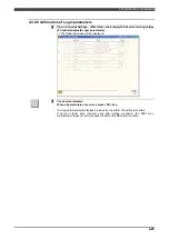
When using the EtherNet/IP Safety communication function, please do not forget to turn
OFF and ON the power after changing the setting of the RMU and completing the approval
operation for the RMU even if there is no modification about the “Safety network
parameters”. Because the communication will not start unless turning OFF/ON the power.
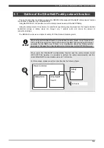
INFO.
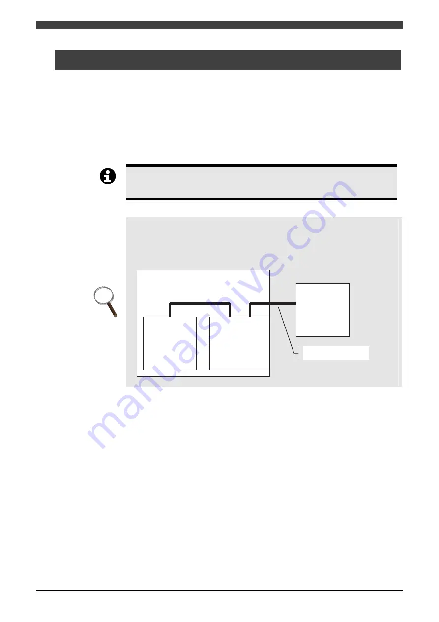
When using this EtherNet/IP communication function and the communication board
(FD11-OP171-B) together, it is possible to perform the safety communication and the
normal EtherNet/IP communication using only 1 LAN cable.
For this purpose, please make the connection like the following figure.
Robot controller
RMU20-30
EtherNet/IP
board
Safety
PLC
LAN cable
Summary of Contents for RMU20-20
Page 2: ......
Page 6: ...Contents 4 ...
Page 8: ......
Page 26: ...1 4 EC DECLARATION OF CONFORMITY FOR MACHINERY 1 18 NOTE ...
Page 68: ...2 9 Enabling RMU 2 40 NOTE ...
Page 70: ......
Page 100: ...3 4 Setting when a slider unit is used 3 30 NOTE ...
Page 102: ......
Page 138: ...4 4Approval 4 36 8 Approval is completed The following screen will be displayed ...
Page 144: ......
Page 154: ...5 4Trouble shooting 5 10 NOTE ...
Page 156: ......
Page 166: ...6 4Trouble shooting 6 10 NOTE ...
Page 168: ......
Page 189: ......

