

3 of 8
www.NabcoEntrances.com
GT1505BumpOutConvenienceWindowInstallationManual
Rev. 12-15-17
P/N C-00208
CHAPTER 3: SCOPE
SECTION 3 .1: To the Installer
The purpose of this manual is to familiarize the installer and purchaser with the proper installation and operation of this system. It is
essential that this equipment be properly installed and operational before the window is used in conjunction with the public. In the
United States, ANSI Standard 156.38 applies. Other local standards or codes may apply. Use them in addition to the ANSI standards.
The owner should determine the window is operating properly and should immediately call for service if there is any malfunction. All
installation changes and adjustments must be made by qualified, NABCO trained technicians.
If after troubleshooting a problem, a satisfactory solution cannot be achieved, please call Nabco Entrances at 1-877-622-2694 between
8 am – 4:30 pm Central time for additional assistance. All installation changes and adjustments must be made by qualified, NABCO
trained technicians.
SECTION 3 .2: Objective
Bumpout Convenience Windows were developed for commercial use in businesses that offer Drive-Thru service and are energy
efficient. The objective is to increase server productivity.
CHAPTER 4: GETTING STARTED
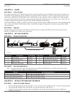
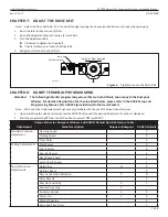
SECTION 4 .1: Common Service Parts
DN 1820
④
②
③
⑤
⑥
⑦
⑧
①
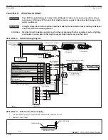
HEADER COMPONENTS
5 6
12
13
14
15
16
Sequential Activation
SQ
Auxiliary Output (Open-Collector)
OUT
5Amax.(0-20V), 3.2Amax.(20-30V)
30V(42.4Vpeak)max.
Contact Output (Class2 Load only)
Common
N/C
N/O
OUT.A
OUT.B
OUT.C
12VDC-(Common)
7
FUNCTION [SLIDING DOOR]
SYMBOL No.
Reduced Opening Switch
11
10
9
8
7
6
5
4
3
2
1
Breakout Detector
Sidelite Presence Sensor
Exterior Activation
BA
62
SLS
M1
H
M0
Holding Beam
Interior Activation
12VDC-(Common)
12VDC+
6B
9DC12V
7
61
Mode Switch (see Mode SW Usage shown left)
HANDY TERMINAL
・
6P
RELA
TED
D
EV
IC
ES
・
16
P
To protect against risk of
fire
or electric shock,use only the
certified NABCO power supply.
WARNING
No.
MOTOR
・
12P
ERROR
POWER
BA
62
H
6B
61
IN
DICA
TO
RS
POWE
R
・
2P
Do not disassemble the control box.
There are no user serviceable parts
inside.
To maintain warranty,repairs must be
made by authorized NABCO facilities.
CAUTION
Adjustments to the door can only be made
with the NABCO Handy Terminal.
Mode SW Usage
Gnd
Gnd
Gnd
Open
Open
Open
Gnd
Open
M0
M1
MODE
TWO WAY
ONE WAY
NIGHT
HOLD OPEN
248901-
Microprocessor Controller
20
VA
C
50/6
0H
z
GYRO TECH
Component
Description
Part Number Component
Description
Part Number
1
Idler Pulley
A-00042
5
U30 Microprocessor Control
V-00020
2
Drive Belt Tensioner
A-00078
6
Motor/Operator Assembly
M-00395
3
Power Supply
A-00717
7
Holding Beam w/Ext Cable
V-00073
4
Photoeye, Optex Assy
A-00129
8
Rocker Switch
A-01356
SECTION 4 .2: Electrical Specifications
Note: All power wiring and component wiring has been pre-installed at the NABCO Factory. Only the Junction Box must be
connected to a power supply by a licensed electrician.
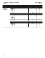
Model
Electrical Specification
GT 1505 without Air Curtain
120 (±10%) AC 50-60Hz, 1/2 Amp
GT 1505 with Unheated Air Curtain
120 (±10%) AC 50-60Hz, 2 Amps
GT 1505 with Heated Air Curtain
120 (±10%) AC 50-60Hz, 15 Amps
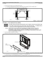
CHAPTER 5: INSTALL THE BUMPOUT WINDOW
SECTION 5 .1: Inspect the Rough Opening
1. Ensure the Rough Opening equals: Package Width + 1/4 inch on each side, and Package height + 1/4 inch on Top and Bottom.
2. Ensure the Rough Opening is level. If the bottom is not level, be prepared to shim the unit.
3. Inspect the area around the rough opening. There should be no obstructions that will interfere with the installation or
performance of the unit.


