MyFlyDream Crosshair Manual Download Page 1

MFD Crosshair automatic landing 

www.MyFlyDream.com 

V1.2 


Performing an automatic landing requires a perfectly tuned plane. 

Please make sure your plane follows routes perfectly before you try to 

land it automatically. "Cross-track error" is very important during the 

landing procedure. About "Cross-track error" please refer to appendix A 

of this document. 


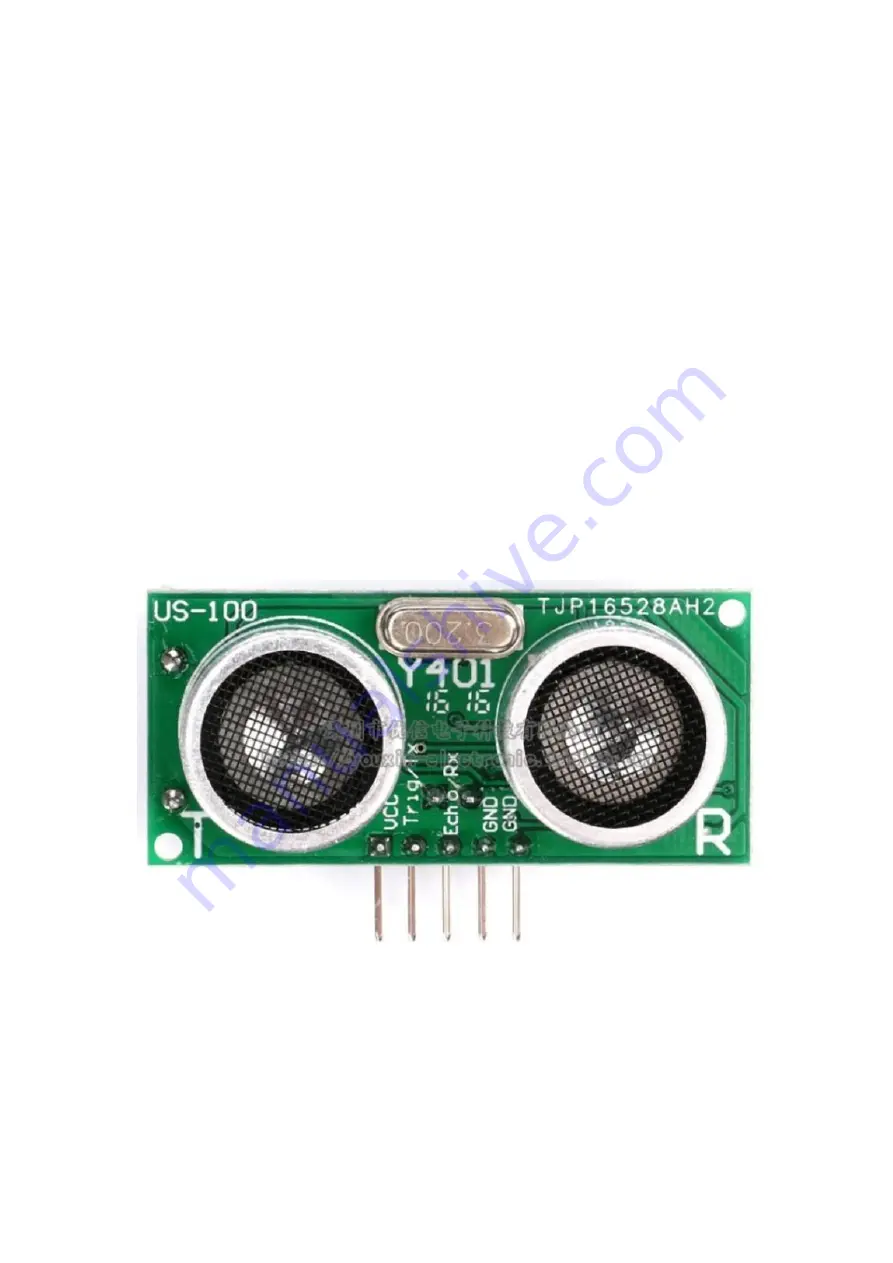
The above photo is the sonar used for auto landing. The "Trig/TX" pin 

connects toD11 pin of the AP. The "Echo/RX" pin connects to D10 pin of 

the flight controller. You also need to 5V power to the sonar. 

We recommend to use the CAN-BUS connector of the harness included 

Summary of Contents for Crosshair

Page 1: ...ically Cross track error is very important during the landing procedure About Cross track error please refer to appendix A of this document The above photo is the sonar used for auto landing The Trig TX pin connects toD11 pin of the AP The Echo RX pin connects to D10 pin of the flight controller You also need to provide 5V power to the sonar We recommend to use the CAN BUS connector of the harness...

Page 2: ... the 24pin connector Port D Insert the yellow wire of the black CAN BUS connector into D10 insert the white one into D11 Once the sonar is connected successfully point the sonar at the wall within 2 meters Another green altitude reading will display below the original white altitude reading The sonar alt reading only displays below 3 meters ...

Page 3: ... adjust the attitude to touch down Please test it several times to ensure it works perfectly The above picture shows a Laser Range Finder connected to a MFD Crosshair AP To activate the Laser Range Finder please set menu SENSORS SETTINGS 2ND ALTIMETER LASER instead of SONAR ...

Page 4: ...Runway Scan function more on it later The AUTO LANDING menu allows you to define three runways but only one of them can be activated at a time Enter Menu AUTO LANDING Runway1 for editing To define a runway you need to specify two points Throughout the landing procedure we will use4 points L1 L2 L3 L4 Please note some of them are on the ground level others are in 3D space and have altitude in addit...

Page 5: ...1 is the location for final touchdown Place the plane at this point and make sure that 12 or more satellites are locked by AP Select the menu L1 SET to let the AP record theL1 position Alternatively you ...

Page 6: ...h the plane is supposed to head for the runway and start to descend to L2 This L3 point is automatically generated by the AP and it lies on the extension of the line connectingL1andL2 The distance between L3 andL2is defined by the user Runway menu L2 L3 distance L3 altitude is also defined by the user Runway menu L3 ALT L4 is the center of a circle on which L3 lies L4 is also automatically generat...

Page 7: ...ght side of the runway before approaching If you set AUTO LANDING RUNWAY1 2 3 TURN LEFT RIGHT RIGHT the plane will use the left side of the runway Each runway has its individual circling direction setting To activate the automatic landing In RTH mode with throttle in low position move the elevator to any corner and draw a square For example upper left upper right bottom right bottom left ...

Page 8: ...ircle Ideally the plane should align to the runway when it reaches L3 If the altitude and distance are close enough to L3 10m the plane will enter the second stage of landing LND 2 Here the plane gradually descends along the L3 L2line and flies towardL2at the speed defined by AUTO LANDING LANDING SPEED Once it reachesL2 the plane enters LND 3 stage It begins to monitor the altitude using the sonar...

Page 9: ...omatically increase progressively At a speed of 35km h the attack angle reaches the value defined by the user WARNING In LND 1 2 3 stages of the landing once the THR stick on the transmitter is moved to a position greater than 50 the plane temporarily enters STB mode The mode switches of the transmitter are still in positions of RTH combination The mode switch doesn t match the flying mode until y...

Page 10: ...ter readings will hardly make any sense at the remote runway In order to solve the above problems and reliably perform automatic landing we need to use a non barometric tool Theoretically sonar can also be used for runway scanning but practically it should be avoided We take runway 1 as an example to explain how it works First activate the runway scan in the menu and change the setting of AUTO LAN...

Page 11: ...t waypoint is executed in WPT mode 2 The altitude of the plane is adjusted to the proper circle altitude and circled around L4 The proper circling altitude is calculated from AltitudeTrim The current ASL from GPS L1 ASL The current barometric altitude ASL stands for Above Sea Level CircleAltitude L4 Altitude AltitudeTrim In this example when the ground pressure changes little the calculation resul...

Page 12: ...e to possible GPS altitude error scanning runway altitude should not be set too low to prevent from crashing on the first attempt It is generally recommended to set an initial scanning runway altitude at about 25 meters In the worst case even if the GPS altitude error is 10 meters it is still quite safe If you expect the battery to retain enough juice by the time of landing you can define a higher...

Page 13: ...tude the scanning distance will increase in a dark environment the plane will circle around L4 again and then perform the next runway scanning at a 5 meters lower then previous altitude If the very first scan is a success no more scans will be performed and the plane will proceed with the normal landing procedure 5 meters altitude reduction between 2 consecutive scans is a constant value and canno...

Page 14: ...ve illustration shows the runway scanning process set to a maximum of 4 times The plane scans the runway from SCAN RUNWAY ALT and descend 5 meters for the next pass With any successful scan the plane proceeds to landing The Youtube link below is a video of a 200 KM long range flight ending with auto landing At about 5 22 the plane enters the scan runway procedure The first attempt of scan was alre...

Page 15: ... is trying the first scan Stage 1 circling around L4 and the attempted altitude is 23 meters relative to the runway It can be seen in this screenshot that after 200 KM of flight we need to use the scan result of the laser altimeter to correct the barometric ...

Page 16: ...so this circling altitude is actually about 32 meters from the ground which is safe From the animation on the upper left corner of this video you can figure out how it works Appendix A What is Cross track error and how to tune the plane to get minimum Cross track error The above diagram describes the concept of Cross track error Usually in WayPoint WPT mode your plane would head for the target and...

Page 17: ... the target in WPT mode To get assistance in tuning the Cross track error please enter the OSD SETTINGS BR Area Bottom Right Area menu and select CROSSTRACK In waypoint mode the chart displayed in the lower right corner indicates the current Cross track error and altitud eerror Cross track error and altitude error will be displayed as curves indifferent colors GREEN and WHITE In the OSD below the ...

Page 18: ...ow We use P I D parameters to control the cross track performance Use AUTOPILOT SETTINGS CROSS TRACK P I D to tune up the plane till you get the best Cross track performance Ideally the plane should fly dead on the route or very slightly oscillate to left and right in long term period Cross track error reading varies between 100 100 or a narrower range ...

Page 19: ...lane flies almost on the route or only with a little oscillating Use a little bit D value to reduce the oscillating If the plane flies alongside the route but still not by the route with a very small Cross track error try to use I value to get it back onto the route For example a reasonable settings combination of mini Crosswind plane is P 9 I 5 D 10 these parameters are in the pre set models Appe...

Page 20: ...nload the runways here you have to pay attention to read the following information The next screenshot shows how we defined a runway 200km away on the launch site To upload a runway you have to click on the map to define 2 points The first point you click in mission planner on the Flight Plan page will be considered as L1 of the runway the point for touchdown The second point you click will be con...

Page 21: ...olumn for these 2 points 3 Fill the index of the runway you want to define in P1 field You can only fill this filed with 1 or 2 or 3 3 You can click the map or drag the place mark to adjust L1 L2 position or edit the Lat Lon field directly In the ALT field you need to fill in the ASL Above Sea Level of L1 and L2 In this example we plan to land on the beach so we define L1 ALT 0m L2 ALT 2m ...

Page 22: ...arameters after uploading Currently User can only change the circling direction in the OSD menu AUTO LANDING RUNWAY X TURN LEFT RIGHT RIGHT CW or LEFT CCW Download a runway from the AP You can also use mission planner to download a runway from the AP Please enter the OSD menu select AUTO LANDING RUNWAY 1 2 3 Click the Read WPs button of mission planner Mission Planner will download the current run...

Page 23: ...enshot you can also see the ASL altitude of L1 L2 L3 L4 36 37 69 69 meters Again please ignore the yellow arrows generated by mission planner They are pointing to the opposite direction of the landing route due to software internal settings that we cannot change If you want to upload it back to the AP please delete L3 L4 before you click the Write WPs button of mission planner ...

Reviews: