background image


mychefcooking.com 

PRODUCT MANUAL    SNACK     -     DT.MP. SN.2202.2 

28 

In the event of a power failure and subsequent restoration of the power supply, the oven 
recovers the firing in progress (if any) and continues with the same parameters as before the 
power failure.  


6.3.


Errors and alarms 

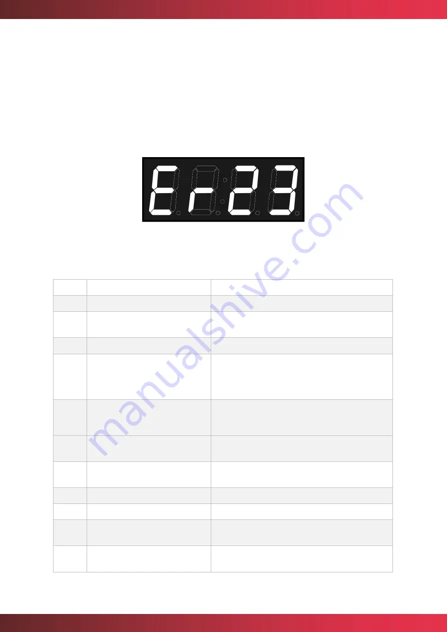
Errors and alarms may occur during the preparation and execution of cooking or washing 
processes. If this is the case, the central display will show the error or alarm code. 


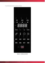
Figure 20. Error indicator 


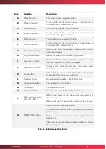
The table below shows the different errors and alarms, as well as possible solutions to them. 

Error 

Internal definition 

Clarification 

NO ERROR 

No error. 

GENERAL PURPOSE INPUT 
ERROR 

Reserved. Not used. 

ERROR OVERTEMPERATURE 

Reserved. Not used. 

ERROR OVERTEMPERATURE PCB 

Overtemperature PCB. Check that the cooling fans 
of the electronics are working properly, that there 
is  enough  space  between  the  back  and  the  wall, 
and that the ambient temperature is not excessive. 

ERROR COMMUNICATION 

Communication 

between 

boards 

is 

not 

responding. Check the cable connecting the power 
board and the control board. 

EEPROM ERROR 

Processor  and  EEPROM  communication  do  not 
work. Check the control board. 

ENGINE ERROR 

Motor  error.  Check  motor  wiring.  Motor 
overtemperature. Motor stuck.  

ALARM WATER 

Reserved. Not used. 

ERROR WASHING 

Reserved. Not used. 

ERROR PROBE1 TEMP SENSOR 
NOT CONNECTED 

Reserved. Not used. 

10 

ERROR PROBE1 TEMP SENSOR 
SHORTED 

Reserved. Not used. 

Summary of Contents for SNACK

Page 1: ...mychefcooking com PRODUCT MANUAL SNACK DT MP SN 2202 2 1 SNACK SNACK AIR SNACK AIR S Product Manual Installation use and maintenance ...

Page 2: ...cation 9 5 INSTALLATION 11 5 1 Electrical connection 11 5 1 1 Three phase connection 400V 3L N 12 5 1 2 Three phase connection 230V 3L 12 5 1 3 Single phase connection 230V L N 13 5 2 Water connection 13 5 2 1 Water inlet 13 5 2 2 Water connection kit to carafe 14 5 3 Steam condensation hood 14 6 USE 15 6 1 Control panel 15 6 1 1 Switching on the equipment 21 6 1 2 Cooking control 21 6 1 3 Start o...

Page 3: ...onization of devices to Google Home 38 7 2 2 Voice commands for oven control 41 7 2 3 Adding automated routines 42 7 3 Support functionalities 45 7 3 1 Reset Wi Fi configuration 45 7 3 2 Show MAC address 45 7 3 3 Unlink service Mychef Control 46 7 3 4 Desktop application for smart control 46 7 4 Table of states 47 7 5 Recipes 47 8 MAINTENANCE 49 8 1 Cleaning 49 8 1 1 Aspiration 49 8 1 2 Door gaske...

Page 4: ...rsonnel who have not received any training skills or experience necessary for the correct operation of the equipment Do not allow children to use or play with the equipment The owner of the equipment is obliged to have this manual read by the personnel in charge of its use and maintenance as well as to keep this manual in a safe place so that it can be used by all users of the equipment and for fu...

Page 5: ...er opening SNACK 4 GN 1 1 upper opening SNACK 4 GN 2 3 lateral opening SNACK 4 GN 1 1 lateral opening External measurements W x D x H mm 620x690x522 760x760x522 620x690x522 760x760x522 Capacity 4 GN 2 3 4 GN 1 1 4 GN 2 3 4 GN 1 1 Table 1 Main features of Mychef SNACK AIR AIR S ovens The maximum recommended food load per GN tray is 3 5kg ...

Page 6: ...ity do not allow it to move while it is connected to the power supply in order to avoid possible damage to the wiring or water inlet pipe If the unit is to be moved or repositioned the wiring and water inlet pipe must be disconnected 3 3 Thermal hazard When the appliance is in operation the door must be opened slowly and carefully to avoid possible burns from steam or hot air escaping from inside ...

Page 7: ...cations During the cleaning process of the combi steamer and in case of formation of aerosols or mist during the handling of the cleaning products wear a mask with particle filter type P2 P3 goggles against splashes and or projections and chemical protection gloves The DA21 cleaning product has been specially formulated for the correct cleaning and protection of Mychef ovens with manual assisted w...

Page 8: ...e point of installation to avoid damage as much as possible It is recommended to keep the original packaging until the equipment is properly installed and operational When moving the equipment and placing it in its workspace the following remarks should be taken into account The dimensions of the different models to pass through narrow places corridors doors narrow spaces See chapter 2 Handling mu...

Page 9: ...t sides o 50mm at the rear o 500mm from the top The equipment must be placed on a Mychef support table or wall bracket If there are sources of heat or steam near the equipment cooker grill griddle fryer pasta cooker kettle tilting frying pan etc these must be at a distance of more than 1 metre Check that the oven is not exposed to hot air or vapours in the areas where the cooling fans are located ...

Page 10: ...llation site Be extremely careful with the cooling zones of the oven If it draws in fumes or hot air this can drastically reduce the life span of the components For the installation of stacked Mychef ovens please follow the instructions supplied with the stacking kit 1000mm 50mm 500m m 50mm 50mm ...

Page 11: ...quipment must be connected to the mains via an all pole circuit breaker with a contact opening distance of more than 3mm Also install a class A residual current device and overcurrent protection Always ensure effective grounding Connect the device to an equipotential bonding system using the contact specially provided for this purpose see equipotential bonding sign on the bottom left hand side of ...

Page 12: ... phase to neutral or ground Check that the installation voltages correspond to those of the equipment The following sub chapters show the possible connection types for Mychef ovens The voltage of each oven can be found on the oven identification sticker 5 1 1 Three phase connection 400V 3L N Colour Cable Brown L1 Black L2 Grey L3 Blue Neutral Green yellow Grounding Table 3 Three phase cable 400V 3...

Page 13: ...8 5 Chlorides Cl less than 30 mg L Chlorine Cl2 less than 0 2 mg L Iron Fe less than 0 1 mg L Manganese Mn less than 0 05 mg L Copper Cu less than 0 05 mg L Conductivity less than 20uS cm Use of decalcifier and Mychef filter mandatory The use of water with characteristics other than those indicated may cause serious problems in the oven components such as corrosion in the baking chamber or the gla...

Page 14: ...are carried out on the water system supplying the oven 5 2 2 Water connection kit to carafe Refer to the installation manual supplied with the water pump kit for installation The water pump is an accessory It can be installed after the oven has been installed 5 3 Steam condensation hood Refer to the installation manual supplied with the steam hood for installation The steam condensation hood is an...

Page 15: ...allows you to manage the humidity temperature time and fan speed parameters and to save programmes In addition it has eight quick access memories The following figures show the control panel of a Mychef SNACK AIR and SNACK AIR S oven Each panel consists of a central screen with displays indicators and buttons Figure 4 SNACK AIR S control panel ...

Page 16: ...mychefcooking com PRODUCT MANUAL SNACK DT MP SN 2202 2 16 Figure 5 SNACK AIR control panel ...

Page 17: ...mychefcooking com PRODUCT MANUAL SNACK DT MP SN 2202 2 17 The functionality of each is explained below Figure 6 Control panel detail A C E C B D F G B I L M N O Q H I J K P ...

Page 18: ...ecreases the selected parameter programme level humidity temperature time or fan speed J Adjustment button Increases the selected parameter programme level humidity temperature time or fan speed K Level button Allows the parameters of a proofer or other accessory to be adjusted from the same control unit L Humidity button Humidity selection button AIR S model only M Temperature button Temperature ...

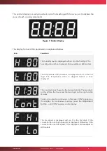
Page 19: ...ture of the chamber is displayed with a T in the first digit The temperature value in degrees Celsius is then displayed The cooking time is shown by the two central dots The two digits on the left are the hours and the two digits on the right are the minutes Cooking can also be continuous In this case CONT appears on the display For continuous cooking press the Adjustment button until CONT appears...

Page 20: ...oven alternately with the current temperature of the cooking chamber The LOAD message indicates that the oven has reached the preheating temperature and the oven can now be loaded Closing the door will start the cooking cycle In the event of an error the first two digits of the display show ER followed by the error number Refer to the error chapter for more information on this It is possible to mo...

Page 21: ...l Temperature and time controlled cooking with temperature adjustment In this mode the oven automatically brings the cooking chamber temperature to the temperature selected by the user so that when the door is opened and the food is loaded the temperature is the desired one The oven automatically calculates the temperature in the cooking chamber and decides whether a preheating process should be c...

Page 22: ...oven will alert the user with a buzzer and indicate Load Figure 10 Charging indicator Once the oven is loaded and the door is closed it will start to count down the cooking time until cooking is complete At this point the time display will show the code word End the oven will beep for one second and the interior light will illuminate until the user finishes cooking by lightly pressing the START ST...

Page 23: ... 10 minutes Figure 11 Example Cooking 90ºC for 10 minutes Figure 12 Oven temperature Cooking phases On the top of the control panel there are three buttons P1 P2 and P3 each corresponding to the cooking phases Associated with each button is an indicator which shows the status of the phase ...

Page 24: ...he button with the inactive phase for two seconds To delete a phase with the oven not cooking press the button with the active phase for two seconds Note that it is not possible to delete the first cooking phase P1 To navigate between phases lightly tap on the phase number you wish to view or edit 6 1 3 Start of the cooking cycle Once the cooking parameters have been selected either in manual mode...

Page 25: ...le At the end of a cooking cycle the appliance signals this status visually and acoustically Specifically A beep sounds The oven chamber light comes on The END keyword appears in the central display until the user finishes cooking To end cooking press START STOP 6 1 5 Speed selection The user can select the convection fan speed that best suits his needs To do this press the fan speed button Then s...

Page 26: ...t the programme with the keys Then select the temperature humidity time and speed parameters for each of the phases Press the PROG key for several seconds until you hear the acoustic signal and the programme is saved The figure below shows programme 1 Figure 18 Example programme 1 To start cooking press the PROG key select the programme you wish to use and press the START STOP key to start cooking...

Page 27: ...phases Then press and hold down the memory key where you want to save the settings for two seconds To start a cooking process stored in a quick memory lightly press the key of the memory you want to execute In firmware versions 1 7 and higher the fast memories correspond to the programmes That is P1 stores the same firing parameters as M1 etc In earlier versions the memories are independent of the...

Page 28: ...O ERROR No error 1 GENERAL PURPOSE INPUT ERROR Reserved Not used 2 ERROR OVERTEMPERATURE Reserved Not used 3 ERROR OVERTEMPERATURE PCB Overtemperature PCB Check that the cooling fans of the electronics are working properly that there is enough space between the back and the wall and that the ambient temperature is not excessive 4 ERROR COMMUNICATION Communication between boards is not responding C...

Page 29: ... used 19 ERROR PROBE6 TEMP SENSOR NOT CONNECTED Reserved Not used 20 ERROR PROBE6 TEMP SENSOR SHORTED Reserved Not used 21 ERROR PROBE7 TEMP SENSOR NOT CONNECTED Reserved Not used 22 ERROR PROBE7 TEMP SENSOR SHORTED Reserved Not used 23 ERROR PROBE8 TEMP SENSOR NOT CONNECTED Chamber probe not connected Check probe and wiring 24 ERROR PROBE8 TEMP SENSOR SHORTED Short circuited chamber probe Check p...

Page 30: ...form Figure 22 Authentication panel Once in the authentication panel select Create account to create a new user account Note The password must be at least 6 characters long To link a device mobile phone tablet or computer it is first necessary to set up a Wi Fi connection in the oven The following section 7 1 2 Wi Fi connectivity explains in detail how to set up this configuration This web address...

Page 31: ...f and wait for a configuration2 web portal to open automatically In this configuration web portal you enter the details of your usual Wi Fi network and the network with which you wish to connect the oven to the Internet SSID In the field Mychef login email you must enter the username that was created earlier 3 7 1 1 Creating a new user 1 It is possible to reset the Wi Fi network configuration at a...

Page 32: ...ntrol We recommend copying the number that appears after the heading MAC Address so that it can be pasted later Figure 24 Wi Fi network configuration screen from different devices Once all fields have been completed select the Save button to save the changes and start the connection 4 If the MAC address of the equipment has not been noted down it is possible to view it on the oven control panel on...

Page 33: ...ing web address https mychef 432df firebaseapp com or QR code log in with the user created in section 7 1 1 and linked to the oven in the section 7 1 2 If you are pairing a device for the first time you will be presented with the button combination shown in Figure 25 To add a new device we select the Add new device button and fill in the form on the Figure 26 form with a name for the device which ...

Page 34: ... change the different parameters that are configured in the linked equipment as well as the actual values of temperature humidity and cooking time It should be noted that when the user makes a modification in this control system there is a time delay between updating the database and sending the modification to the equipment 7 1 4 Control panel In the Figure 27 you can see the control panel of the...

Page 35: ...mychefcooking com PRODUCT MANUAL SNACK DT MP SN 2202 2 35 Figure 27 Detail of the control panel ...

Page 36: ...ays the cooking parameters of this phase If the text on the button appears as if it is disabled it means that the phase is not active J Checkbox phase activation Deselect if you want to deactivate a phase Phase 1 is always active K Oven target temperature input indicator Set Point Allows you to enter the desired temperature value in the range 30 300 C for manual cooking or indicates the target tem...

Page 37: ...n the recipe selection box N to the oven V Delete recipe button Deletes the recipe selected in the recipe selection box N W More information button Opens a window with information about the device the user linked to the device the minutes of operation of the oven and the temperatures of the electronics of the device X Add new device button Allows you to link a new device See section 7 1 3 Y Delete...

Page 38: ...nd download the Google Home and Google Assistant app Figure 28 Google applications needed Once the two applications are installed start Google Home and follow the steps below 1 On the home screen of the app select Add and then Configure device Figure 29 Screenshots steps to follow Google Home application 7 At the moment Mychef Smart Voice Control is only available entirely in English so it is nece...

Page 39: ...in the control web application 8 See section 7 3 3 It is possible that in some cases the server is busy or that a message appears informing that the synchronization could not be carried out the message should be omitted if the linked ovens appear on the start screen if they do not appear repeat all the steps in this section Whenever an oven is added or removed in the control web application the Go...

Page 40: ...K DT MP SN 2202 2 40 Figure 31 Authentication server screen and messages appearing while validating and synchronizing information Figure 32 Authentication server screen and messages appearing while validating and synchronizing information ...

Page 41: ...e What mode is Mychef set Is Mychef humidity X mode set Set all ovens mode to Humidity X TIME CONTROL X 0 99 hours 0 5940 minutes 0 356400 seconds Run Mychef for X Set Mychef timer to X Start Mychef for X How many minutes are left on Mychef Cancel Mychef timer How many minutes are left on ovens Increase Mychef timer X Decrease Mychef timer X FAN CONTROL X High Low Set Mychef fan speed to X Set Myc...

Page 42: ...y from the Google Assistant app or via any Google Assistant enabled device such as a Google Home speaker Figure 33 Different voice commands understood and executed by the Assistant 7 2 3 Adding automated routines It is also possible to add routines to Google Home so that different actions can be performed with a single voice command Below is an example where just by saying Cook Pizza Google Home w...

Page 43: ...mychefcooking com PRODUCT MANUAL SNACK DT MP SN 2202 2 43 Figure 34 Google Assistant app screenshot 2 Then manage routines and click on the add icon Figure 35 Google Assistant Routines capture ...

Page 44: ...n this routine 7 2 2 that you want the oven to perform in this routine For this example they will be the following10 Turn Mychef on Set Mychef temperature to 260 Set Mychef mode to Humidity Low Start Mychef for 17 minutes Start Mychef Figure 36 Routine settings in the Google Assistant application 10 In these commands the word Mychef appears to refer to the oven in question but this word can be sub...

Page 45: ...TART STOP button Once switched off press and hold the fan icon or M4 on the front panel until you hear a Click See if the device s Wi Fi Hotspot appears if not repeat these actions again 7 3 2 Show MAC address It is possible to display the MAC address of the device once the Wi Fi connection to the device has been configured as follows Switch off the oven by pressing and holding the START STOP butt...

Page 46: ...e account simply select the linked account and choose unlink Figure 38 Last window concerning the steps to follow to unlink the account from the service 7 3 4 Desktop application for smart control If the web control application is accessed via the Google Chrome browser it is possible to download the page as an application either on a mobile device or on a computer Computer Go to the menu at the to...

Page 47: ...progress Preheating The equipment is switched on and preheating Adjust The equipment is switched on and has reached the heating temperature Washing The equipment is switched on and performing a wash Error The device shows an error on the central display Connecting It is trying to connect with the oven Table 11 Different statuses that can be displayed on the control panel 7 5 Recipes The remote con...

Page 48: ...the data previously entered at the time it was created and it will be sufficient to modify the data by the new desired parameters Figure 41 Recipe creation form If a recipe is selected the cooking parameter input fields will be locked with the values of the recipe in question to change the cooking values again select Manual cooking ...

Page 49: ... equipment The table below shows the frequency with which the different parts of the equipment must be cleaned Part of the team Frequency Inside the chamber Daily Compartment behind the suction plate Daily Door gasket Daily Outer plates of the equipment Daily Door water drain Weekly Inner outer door compartment Weekly Table 12 Cleaning frequencies in Mychef ovens Before starting any cleaning progr...

Page 50: ...ce the cleaning of the chamber has been completed the washing process will continue with the gasket that ensures the tightness of the chamber It is important that this part of the oven is clean and does not have any pieces of food embedded in it so that it can seal the chamber well and heat water or steam cannot escape when it is in operation To clean this rubber seal simply wipe with a cloth damp...

Page 51: ...hols or solvents as they may attack the metals or plastics of the control panel 8 1 5 Front water drain This is the part that allows any water droplets that may fall from condensation from the steam from the inner door to run into the drain so it is important to keep this drip tray clean and unobstructed Remove any pieces of food that may have fallen before cleaning Then wipe with a cloth dampened...

Page 52: ...tainless steel 8 2 Preventive maintenance Mychef ovens are designed for intensive and long lasting operation To ensure this in addition to regular cleaning preventive maintenance must be carried out This preventive maintenance is specifically designed to prolong the life of your Mychef oven minimise energy and water usage and ensure uninterrupted excellent cooking quality This maintenance programm...

Page 53: ...ychef maintenance programme 2000 4000 6000 8000 10000 12000 14000 16000 18000 20000 Revision A Firmware update X X X X X X X X X X Water hardness check X X X X X X X X X X Cleaning cooling fans X X X X X X X X X X Electronic cleaning X X X X X X X X X X Drain pan and siphon cleaning X X X X X X X X X X Weatherstripping replacement and door adjustment X X X X X X X X X X Revision B Pathogen inactiv...

Reviews: