210208_A
mychefcooking.com
10
PRODUCT MANUAL EVOLINE - DT.MP.EV.2103.2
5.
INSTALLATION
5.1.
Electrical connection
Check that the voltage reaching the point where the oven is to be switched on corresponds
to the operating voltage of the equipment.
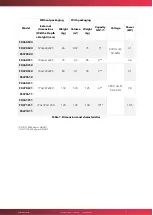
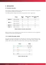
The following table indicates the electrical characteristics of each regenerator:
Voltage
Power
(kW)
Rated current
(A)
Cross-section cable
(mm
2
)
5GN 2/3
230/L+N/50-60
3.1
14
1.5
5GN 1/1
230/L+N/50-60
3.6
16
1.5
400/3L+N/50-60
5.1
8
1.5
6GN 1/1
400/3L+N/50-60
7.8
12
1.5
10GN 1/1
400/3L+N/50-60
10.5
16
1.5
Table 4. Electrical connection characteristics
Before carrying out any electrical work, make sure that no electrical current is supplied at
the point of connection of the equipment.
5.1.1.
Evoline three-phase models
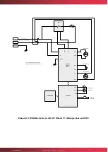
For proper connection after positioning, the device has a five-wire, approximately 2 m long,
H05RN-F type cable. The phases (L1, L2, and L3) are color brown, grey, and black. The
phases order can be inverted. The neutral is blue, and the grounding is yellow-green.
Color
Cable
■
Green-yellow
Grounding
■
Blue
Neutral
■
Brown
L1
■
Grey
L2
■
Black
L3
Table 5. Cable color code

