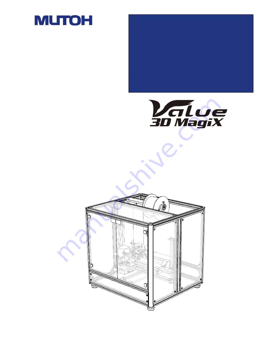
MF-1100
Thank you for buying the Value 3D MagiX MF-1100. Please read
this manual before using this products for long term usage.
This
product has been adjusted before shipment from the factory.
OPERATION
MANUAL
Page 1: ...100 Thank you for buying the Value 3D MagiX MF 1100 Please read this manual before using this products for long term usage This product has been adjusted before shipment from the factory OPERATION MAN...
Page 2: ...When the date of purchase purchaser s address purchaser s name and the name of the store of purchase is not entered in the warranty or these have been altered l When the main unit has been resold m R...
Page 3: ...to the Printer 18 8 Initial Setup of the Control Software 21 9 Preparing the Filament 23 10 Basic Operations 25 Details of Pronterface 33 11 Printing from MicroSD Cards 35 12 Reattaching Polyimide Ta...
Page 4: ...This indicates that mishandling of the product by the user may result in injury or damage to property Explanation of Graphic Symbols Used in This Manual Graphic Symbol Meaning PROHIBITED This indicate...
Page 5: ...5 Never use MUTOH ENGINEERING INC products for making objects that violate the Ordnance Manufacturing Act Swords and Firearms Control Law known more by its official name the Law to Control the Possess...
Page 6: ...all accessories are provided in the packing case Q ty 1 pc 1 pc 1 pc 4 sheets Accessory Name AC adapter for main unit 1 pc AC adapter for LED lighting See 14 Using the MagiX LED Light PLA filament wh...
Page 7: ...7 3 Names of Parts Front Inside Front side Adjuster foot 4 locations Top Filament shaft Filament stopper Filament guide Print head Heat table...
Page 8: ...8 Left side panel Micro SD card slot USB terminal Power terminal...
Page 9: ...board packing case 2 Remove the pad from the top and the corner pads on all four corners CAUTION When using a box cutter to open the cardboard packing case take care not to insert the blade of the box...
Page 10: ...Filament 4 Take out the accessories The accessories are secured in place by tape under the main unit CAUTION This work should be performed by at least two personnel When removing the main unit hold t...
Page 11: ...ries are provided in the packing case 5 Install at a sturdy level and stable location Q ty 1 pc 1 pc 1 pc 4 sheets Accessory Name AC adapter 1 pc AC adapter for LED lighting PLA filament white 1 kg US...
Page 12: ...ly removed A power switch is not provided on the main unit So remove the power plug when the main unit is not to be used for a long time Install the main unit at a level and stable location where it w...
Page 13: ...lation site 2 Turn the top ring to adjust the height of the adjuster feet 3 To lower the feet turn left of the top ring To left the feet turn right of the ring In the initial state the feet are raised...
Page 14: ...oor 2 Turn the nut and screw of the fixing bracket installed on the left side of the print head to unfasten the bracket and remove the bracket while opening it out 3 A fixing bracket is attached to th...
Page 15: ...l on the left side panel of the main unit 2 Insert the other end of the USB cable into the USB terminal on the PC USB terminal CAUTION Allow sufficient slack in the cable If the cable is taut vibratio...
Page 16: ...dapter main unit 2 Insert the round plug of the AC adapter into the power terminal on the side of the main unit Power terminal 3 Insert the plug of the AC adapter into the power outlet Firmly insert t...
Page 17: ...tware comprises two pieces of software the equipment control software Pronterface and the model slicer Slic3r The following describes the procedure from software download through to installation 1 Acc...
Page 18: ...oftware startup bat in the Pronterface folder and Slic3r exe in the Slic3r folder Creating a shortcut on the Desktop Creating a shortcut on the Desktop 5 Create shortcuts for the above files on the De...
Page 19: ...o start the initial setup double click the Slic3r setup installation bat file in the Slic3r setup file folder The batch file is started up and the initial setup is executed 2 Start up the slicer and t...
Page 20: ...the driver access the web site of the following manufacturer Name of manufacturer Corporate Headquarters Future Technology Devices International Limited URL http www ftdichip com 2 In the menu on the...
Page 21: ...tallation file CDM v2 12 00 WHQL Certified exe To start up the file right click on the file and then click Run as administrator Reference 1 The COM number can be checked Windows 7 OS 1 Right click and...
Page 22: ...22...
Page 23: ...unication speed click the Connect button If the screen remains grayed out even by pressing the Connect button this means that the connection to the COM port has not been made Change the COM port value...
Page 24: ...ing nut and check the distance between the table and head again 7 Click the Z direction button to raise the head about 5 cm from the table 8 Next prepare the filament CAUTION In low air temperatures f...
Page 25: ...easily The melting temperature of different types of filament varies So we recommend changing the heater head when using different types of filament Please note that guarantees cannot be made when out...
Page 26: ...for example is as follows 1 Heat up the nozzle to a temperature matched to the filament that is currently attached In Pronterface enter the temperature at the Nozzle item and click the Set button For...
Page 27: ...STL data to be printed using commercially available 3D CAD or modeling software How to create basic G code data Prepare the STL data of the model to be printed 1 Start up Slic3r Preparation of model...
Page 28: ...hape of the model can be checked by double clicking the external profile 5 Change the settings as required For example to change the thickness of a layer modeling pitch set the value of Layer Thicknes...
Page 29: ...ted up and the settings required at execution of that file are set in advance You can also make Cooling related settings regarding how the fan should be used For ABS set a weaker fan value Reference T...
Page 30: ...28 1 A modeling pitch of 0 05 mm is not guaranteed in all printing operations...
Page 31: ...ked Item Check Table size X 200 Y 200 Print center X 100 Y 100 Types of firmware G code MF 1000 etc 8 Return to the Model Layout tab window and click the Output G Code button 9 The Save G Code File wi...
Page 32: ...e data Exit Slic3r Select File F and click Exit Next perform printing using the G code file you created 12 Check the following items Power is supplied to the equipment from the AC adapter The PC is co...
Page 33: ...ted and click the Open button When reading of the G code file is completed the print pass route is displayed in the grid in the center Also the following details are displayed in the fields on the rig...
Page 34: ...layed Hours minutes and seconds are displayed at CAUTION If the previous printed model or other obstacles are on the heat table the equipment and printing will not function properly This also may resu...
Page 35: ...lly since it is still attached to the table The printed model can be easily removed from the table once the table has cooled down If you find it difficult to remove the printed model from the table yo...
Page 36: ...e printing is paused 4 Off button This turns the motor heaters and fans OFF Be sure to disconnect the power plug when the equipment is not to be used for a long time 5 Motor OFF button This turns the...
Page 37: ...35 of vertical movement of the print head...
Page 38: ...OFF 8 Nozzle heat table temperature display panel This panel displays the current and target temperatures of the nozzle and heat table in the form of a line chart The line chart is displayed on the te...
Page 39: ...rd inside the printed circuit boards SD cards through to SDHC cards are supported SDXC cards cannot be used 3 Start up the control software Pronterface and select SD Card Print from SD Card 4 The cont...
Page 40: ...l off the used polyimide tape from the heat table 3 Lightly wipe the top of the heat table with OA cleaner for LCD displays or cleaner for TV screens for example 4 Attach new polyimide tape to the hea...
Page 41: ...difficult to remove use a tool to press in the tabs Photograph on right 3 Remove the hexagon socket head cap bolts from the metal panel securing the head in place with a 2 5 mm hexagonal wrench 4 Rem...
Page 42: ...40 and remove the resin The Z axis height cannot be adjusted properly with resin still attached to the tip of the head...
Page 43: ...ent is finished tighten the fixing nut and check the distance between the table and head again 10 This completes replacement of the head and adjustment of the Z axis Head falls Head rises Head section...
Page 44: ...e MagiX LED Light The MF 1100 has a built in LED light as standard To turn the LED light ON connect the AC adapter to the jack at the bottom on the left side Front Position of jack Insert into jack To...
Page 45: ...s This means that a G code file contains all elements such as modeling pitch temperature conditions and wall conditions STL file STL stands for STereoLithography and is the most widely used polygon fo...
Page 46: ...ect button to establish a connection If a connection is not made check the COM port number or the cable connection The G code file has not been read to the control software Pronterface Read the G code...
Page 47: ...ht of the heat table using the four height adjusting screws so that the table is parallel The equipment runs out of filament during printing Stop printing by the Pause button in Pronterface replace wi...
Page 48: ...erials used ABS PLA dia 3 0 mm 1 75 mm Supported OS Windows 7 Windows 8 Windows 8 1 Recommended PC specifications CPU Pentium 4 or later memory 2 GB or more Software Control software Pronterface Japan...
Page 49: ...is resold March 5 2015 Drawings for table cleaning added March 16 2015 AC adapter for LED light also is provided as an accessory May 7 2015 Use an English name comprising single byte letter and number...
Page 50: ...48 44...
Page 51: ...Drafted by and copyright owned by MUTOH ENGINEERING INC Reproduction of this document is strictly prohibited Value3D MagiX Customer Center TEL 0120 147 610 Mail info 3d mutoheng jp May 2015 May 13 20...