Munsch MPC-B series Operating Instructions Manual Download Page 1

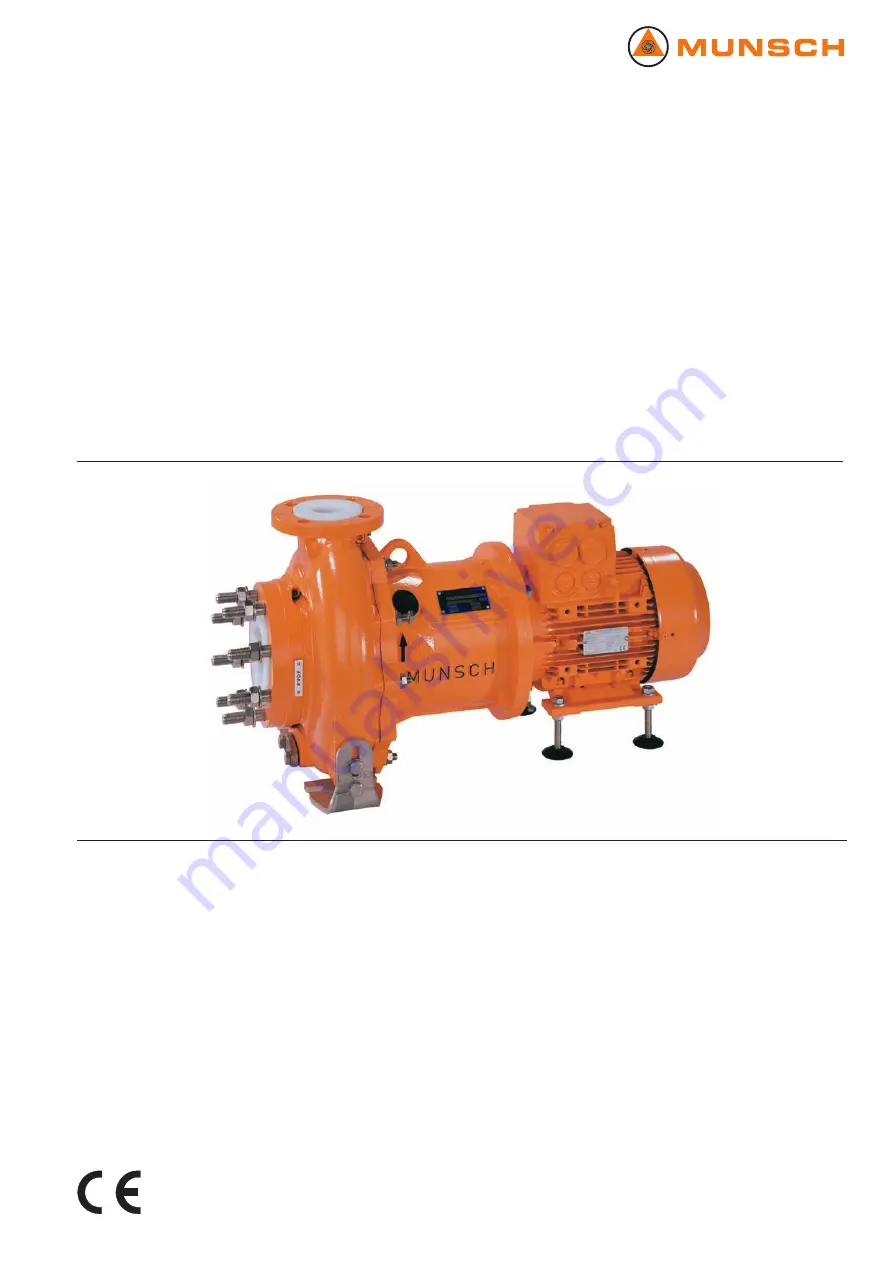
Standard Chemical Pump

Operating instructions

MPC-B series

Version

BA-2006.03

Print-No.

01

VM-No.

EN

Munsch Chemie-Pumpen GmbH
Im Staudchen
56235 Ransbach-Baumbach
Germany
Phone: +49 (0) 26 23-8 98-90
Fax: +49 (0) 26 23-8 98-95
E-mail: [email protected]
Internet: http://www.munsch.de

We reserve the right to make technical changes.

Summary of Contents for MPC-B series

Page 1: ...Version BA 2006 03 Print No 01 VM No EN Munsch Chemie Pumpen GmbH Im Staudchen 56235 Ransbach Baumbach Germany Phone 49 0 26 23 8 98 90 Fax 49 0 26 23 8 98 95 E mail munsch munsch de Internet http ww...

Page 2: ...nded 15 5 5 Connecting the pipes 15 5 5 1 Installing auxiliary pipes 15 5 5 2 Installing the suction pipe 16 5 5 3 Installing the pressure pipe 16 5 5 4 Checking that the pipe connections are stress f...

Page 3: ...ptying optional 33 Fig 20 Fluid connection optional 33 Fig 21 Socket loads at the pump 34 List of tables Tab 1 Target groups and their duties 4 Tab 2 Other applicable documents and their purpose 4 Tab...

Page 4: ...cuments especially all safety instructions and warnings Tab 1 Target groups and their duties 1 2 Other applicable documents Document Purpose ATEX additional instructions Operation in potentially explo...

Page 5: ...Warnings and consequences of non observance Symbol Meaning Safety warning sign Observe all information indicated by the safety warning sign to avoid injury or death Instruction 1 2 Multiple step inst...

Page 6: ...exceed the permissible density order data sheet A lower density is allowed Adapt the auxiliary systems accordingly Adhere to the limits for solids content and grit size when pumping solids carrying f...

Page 7: ...btain the manufacturer s approval prior to carrying out any modifications repairs or alterations during the warranty period Only use original parts or parts that have been approved by the manufacturer...

Page 8: ...le 1 Pump type 2 Serial number 3 Year of construction 4 Pump head 5 Density 6 Torque 7 Speed 8 Power consumption 9 Flow rate 10 Impeller diameter 3 1 2 ATEX plate 1 2 Fig 2 ATEX plate example 1 Explos...

Page 9: ...and function 3 2 Layout 3 2 4 5 6 8 7 1 Fig 4 MPC B layout 1 Impeller 2 Housing armour 3 Volute casing 4 Motor 5 Drive shaft 6 Drive rotor 7 Pump rotor 8 Plain bearing bracket EN 01 BA 2006 03 MPC B s...

Page 10: ...attracted by magnetisable metal parts Keep magnetically sensitive objects at least 150 mm away from the magnetic coupling 4 1 1 Unpacking and inspection on delivery 1 Unpack the pump group on delivery...

Page 11: ...in the process 4 4 Disposal Plastic parts can be contaminated by poisonous or radio active pumped liquids to such an extent that cleaning is insufficient DANGER Risk of fatal injury and material dama...

Page 12: ...te Make sure the installation site meets the following condi tions Pump freely accessible from all sides Sufficient space for installation removal of the pipes and for maintenance and repair work espe...

Page 13: ...er when using chemical anchors 3 Set the pump group down on the foundation sinking the foundation bolts into the prepared anchoring holes 3 2 1 2 Fig 7 Setup with foundation 4 Use steel washers to ali...

Page 14: ...damage due to magnetic field Make sure no one with a heart pacemaker performs any work on the pump Secure the workplace and cordon it off if necessary Ensure staff with heart pacemakers keep a minimum...

Page 15: ...rovisions for isolating and shutting off the pipes For maintenance and repair work Fit stop valves in the suction pipe and pressure pipe Enable measurements of the operating conditions 1 For pressure...

Page 16: ...injury due to electric shock Have all electrical work carried out by qualified electricians only DANGER Risk of fatal injury and material damage due to magnetic field Make sure no one with a heart pac...

Page 17: ...e 6 1 4 Filling and bleeding Auxiliary operating systems ready for operation if available WARNING Risk of injury and poisoning due to hazardous pumped liquids Safely collect any leaking pumped liquid...

Page 18: ...ch the running pump Do not carry out any work on the running pump Allow the pump to cool down completely before starting any work DANGER Risk of injury and poisoning due to pumped liquid spray ing out...

Page 19: ...ccordance with environmental rules and requirements Take the following measures if operation is interrupted Pump is Measure shut down for a prolonged period Take measures according to the pumped liqui...

Page 20: ...magnetisable metal parts Keep magnetically sensitive objects at least 150 mm away from the magnetic coupling 1 In the event of a downtime of more than a year Table 6 Measures after long storage times...

Page 21: ...sure no parts of the magnetic coupling are able to be attracted by magnetisable metal parts Keep magnetically sensitive objects at least 150 mm away from the magnetic coupling DANGER Risk of injury du...

Page 22: ...ttracted by magnetisable metal parts Keep magnetically sensitive objects at least 150 mm away from the magnetic coupling DANGER Risk of injury due to running pump Do not touch the running pump Do not...

Page 23: ...ng any work Make sure the pump is unpressurised Empty the pump safely collect the pumped liquid and dispose of it in accordance with environmental rules and requirements 7 3 1 Returning the pump to th...

Page 24: ...t cant ing Dismount the pump sectional drawing 2 Undo the fixation bolts on the housing feet 187 3 Lift the pump out of the installation 4 1 2 Lifting Page 10 7 3 3 Undoing connections if available Fl...

Page 25: ...10 412 1 Fig 14 Dismounting the impeller plain bearing bracket and pump rotor 5 Unscrew the socket head cap screw 914 1 with Schnorr spring washer 938 6 Pull off the impeller 230 with thrust bearing...

Page 26: ...7 4 1 Preparing the installation 1 Observe the following for the installation Replace worn out parts with original spare parts Replace gaskets inserting them in such a way that they cannot rotate Obs...

Page 27: ...hnorr spring washer 938 10 Insert the can 820 and can insert 830 in the intermediate lantern146 11 Screw the eye bolt in the tap hole for the impeller screw 906 and thread in the crane cable 12 Insert...

Page 28: ...low Use this number to find the cause and remedy in the troubleshooting table Fault Number Pump not pumping 1 Pumping rate insufficient 2 Pumping rate too high 3 Pumping pressure too low 4 Pumping pre...

Page 29: ...ned wide enough Open the pressure side fitting X X X X Pressure pipe blocked Clean the pressure pipe X X X X Pump running in the wrong direction Swap any two phases at the motor X X X Motor speed too...

Page 30: ...y clotted or encrusted Dismount the pump Clean the components X X Antifriction bearing in motor defective Replace the antifriction bearing X Lubricant too much not enough or unsuitable Reduce top up o...

Page 31: ...Bearing seat 400 xxx Gasket 412 xxx O ring 529 xxx Bearing sleeve 545 Bearing bush 550 xxx Disc 554 xxx Washer 560 xxx Pin 708 20 Fluid connection 801 Flange motor 820 Can 830 Can insert 858 Drive rot...

Page 32: ...314 914 1 906 938 940 7 412 4 902 2 412 69 230 920 3 554 15 102 339 155 146 560 560 5 859 412 16 314 820 830 858 901 16 940 8 914 11 216 800 550 3 940 3 554 25 901 18 132 939 8 554 1 901 1 412 1 Fig 1...

Page 33: ...00 1000 Tab 13 Ambient conditions 9 2 2 Noise pressure level Measuring conditions Distance to pump 1 m Operation cavitation free Motor IEC standard motor Tolerance 3 dB Lower noise motors are availabl...

Page 34: ...alkaline soap suds steam blast for individual components only Other Benzine wax solvents diesel petrol alkaline cleaners Tab 17 Cleaning agents 9 2 5 Socket loads according to ISO 5199 Fz Mz Z Fx Mx X...

Page 35: ...r more Part no Part designation Set Quantity of spare parts 230 Impeller 1 1 1 1 2 2 2 20 Plain bearing complete 1 1 1 2 2 2 3 30 321 1 Radial ball bearing 1 1 1 2 2 2 3 30 321 2 Radial ball bearing 1...

Page 36: ......

Page 37: ......

Reviews: