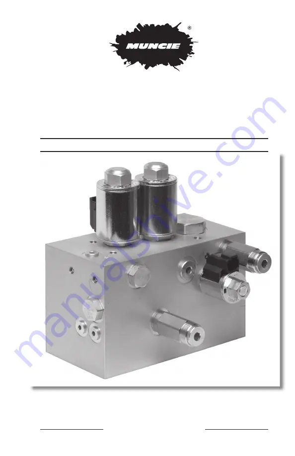
MESP-202H
INSTALLATION INSTRUCTIONS
AND OWNER’S MANUAL
FEATURES • VALVE FUNCTIONS • ADJUSTMENTS • SCHEMATICS
HF42407-07 and
HF51912-09
Muncie Power Products, Inc.
Page 1: ...MESP 202H INSTALLATION INSTRUCTIONS AND OWNER S MANUAL FEATURES VALVE FUNCTIONS ADJUSTMENTS SCHEMATICS HF42407 07 and HF51912 09 Muncie Power Products Inc ...
Page 2: ...Center Schematic 7 Original Load Sense Schematic 8 Revised Cartridge Designations Functions and Part Numbers 9 Revised Open Center Schematic 10 Revised Load Sense Schematic 11 Relief Valve Adjustment 12 Detailed Description of MESP 202H 13 15 Original MESP202H HF42407 07 Revised MESP202H HF51912 09 Changes to revised model 1 Eliminated CV2 HF42407 07 2 Moved PGP gage port from side on HF42407 07 t...
Page 3: ...ILE 2 DESIGN OPTIONS Load Sense variable displacement pumps or Open Center fixed dis placement pumps 2 ADJUSTABLE RELIEF VALVES One inlet relief and one output relief HYDRAULIC SPECIFICATIONS Maximum Inlet Flow 30 GPM Maximum System Pressure 3 000 PSI Unloaded Pressure Drop 40 PSI AT 25 GPM Auger Flow Proportional 15 GPM Pressure Compensated Spinner Flow Proportional 7 GPM Pressure Compensated Mai...
Page 4: ...4 ORIGINAL MESP 202H WORKPORTS P S T2 P2 DESIGNATION DESCRIPTION SIZE SAE T TANK 12 T2 TANK 12 P PUMP 12 P2 PUMP 16 A AUGER 12 S SPINNER 12 LS LOAD SENSE 4 PGP PUMP GAGE PORT 6 HF42407 07 PGP T A LS ...
Page 5: ...5 REVISED MESP 202H WORKPORTS APRIL 1 2009 DESIGNATION DESCRIPTION SIZE SAE T TANK 12 T2 TANK 12 P PUMP 12 P2 PUMP 16 A AUGER 12 S SPINNER 12 LS LOAD SENSE 4 PGP PUMP GAGE PORT NPTF HF51912 09 A S T P ...
Page 6: ...Pressure Compensated Flow Control NXPV7030A0N00 LS1 Load Sense Shuttle NXLS08300N00 PV2 Auger Pressure Compensated Flow Control NXPV72200N00 EV1 Pump Unloader NXEV16S340N10 RV2 Main System Relief NXRV0820H0N3322 CV2 LS Check Valve NXCV04200N05 CV1 Boost Pressure Check NXCV08200N270 SV1 Pump Unloader Pilot NXSV08210N00 RV1 Auger Spinner Relief NXRV0820H0N1820 ...
Page 7: ... DESIGNATION DESCRIPTION SIZE SAE T TANK 12 T2 TANK 12 P PUMP 12 P2 PUMP 16 A AUGER 12 S SPINNER 12 LS LOAD SENSE 4 PGP PUMP GAGE PORT 6 HF42407 07 HF42407 07 PORTS HF42407 07 VALVES SV1 RV1 RV2 PV2 PV1 LS1 EV1 CV1 ORF1 P2 T P T2 S A LS PGP CV2 ...
Page 8: ...2 P PUMP 12 P2 PUMP 16 A AUGER 12 S SPINNER 12 LS LOAD SENSE 4 PGP PUMP GAGE PORT 6 HF42407 07 HF42407 07 PORTS RV1 RV2 PV2 PV1 LS1 EV1 ORF1 P2 T P T2 S A LS PGP CV2 CP1 CP2 HF42407 07 VALVES SV1 Replaced with CP1 NXCP0820N in LS Configuration CV1 Replaced with CP2 NXCP0820N in LS Configuration ...
Page 9: ...inner Pressure Compensated Flow Control NXPV7030AM0N00 LS1 Load Sense Shuttle NXLS08300N00 PV2 Auger Pressure Compensated Flow Control NXPV7220M0N00 EV1 Pump Unloader NXEV16S340N10 RV2 Main System Relief NXRV0820H0N3322 CP1 Cavity Plug NXVC042 CV1 Boost Pressure Check NXCV08200N270 SV1 Pump Unloader Pilot NXSV0821K0N0 RV1 Auger Spinner Relief NXRV0820H0N1820 ...
Page 10: ...10 REVISED MESP 202H OPEN CENTER SCHEMATIC 4 1 09 HF51912 09 SV1 RV1 RV2 PV2 PV1 LS1 EV1 CV1 ORF1 P2 T P T2 S A LS PGP CP1 ...
Page 11: ...ESP 202H LOAD SENSE SCHEMATIC 4 1 09 HF51912 09 CP2 RV1 RV2 PV2 PV1 LS1 EV1 CP3 ORF1 P2 T P T2 S A LS PGP CP1 CV1 Replaced with CP3 NXCP0820N in LS Configuration SV1 Replaced with CP2 NXCP0820N in LS Configuration ...
Page 12: ... The tools required to adjust the relief valves include a 5 16 Allen drive and a Allen drive 2 Remove the caps from both of the relief valves Oil may seep out of these cartridges when the caps are removed and the system is operating 3 Place A gage in the PGP port If not accessible tee a gage in between the Pump Outlet and the Pressure Port P of the MESP202H 4 Start the truck and Deadhead flow at e...
Page 13: ...sure will show at PGP The path to tank is opened by pump pressure being applied to the left side pilot of EV1 which forces it open The right side pilot line of EV1 is drained to tank through SV1 Unloader Solenoid Valve to allow this to happen Solenoid Valve SV1 Unloader solenoid valve SV1 is a normally open two position two way solenoid operated cartridge When its solenoid is not energized it prov...
Page 14: ...2 has been set The pressure of the pump and the left side of EV1 will build slightly higher and force EV1 to begin to open and provide a tank path for the pump Orifice ORF1 Load sense drain orifice ORF1 provides a controlled drain for the load sense pilot line EV1 control pilot Its function is to ensure that the pressure cannot be trapped in this pilot and result in EV1 not being able to fully ope...
Page 15: ... conveyor load pressure demands If the pressure difference goes too high the compensator stage will squeeze down to prevent extra flow from shooting through the proportional valve orifice setting The basis of stable flow control requires this feature Relief Valve RV1 Spreader pressure relief RV1 limits the pressure of the spreader motor circuits This gives independent protection to the motors from...
Page 16: ... 765 284 6991 info munciepower com www munciepower com Specifications are subject to change without notice Visit www munciepower com for warranties and literature All rights reserved Muncie Power Products Inc 2009 A Member of the Interpump Group IN09 05 Rev 02 18 ...