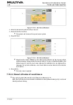
Figure. 7.10.1.1. - 262. Calibration of the machine seeding position sensor
The number (4) indicates the sensor position. This is raw data from the controller.
2. Press SET (3).
3. Raise the machine into the transport position.
The blue bar (1) moves along the scale.
4. Press SET (2).
7.10.2. Travel distance calibration
7.10.2.1. Travel distance calibration while driving
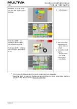
The control system PIN code for travel distance calibration is “5”.
Figure. 7.10.2.1. - 263. Travel distance calibration 1
1. Press SET A (1).
2. Drive the desired distance.
Operation and maintenance manual
FX300 and FX400 SeedPilot
1.00
190 (208)
Summary of Contents for FX300 SeedPilot
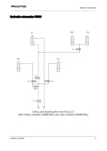
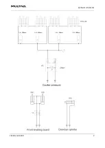
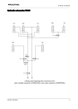
Page 200: ...Hydraulic schematics FX300 and FX400 1 Hydraulic schematics FX300...
Page 201: ...Hydraulic schematics FX300 and FX400 2...
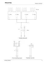
Page 202: ...Hydraulic schematics FX300 and FX400 3 Hydraulic schematics FX400...
Page 203: ...Hydraulic schematics FX300 and FX400 4...
Page 204: ...Electrical schematics FX300 and FX400 1 Electrical schematics...


