Instruction manual (Translation of the original instructions)
CM150032EN - 16.06.15 - 05 (11.07.18)
45
/76
Self-moving Compact wheel loader, articulated frame, equipped with
multipurpose quick coupler, MULTIONE 6 Series
MultiOne SRL
OPERATION -8
8.3.3.2 Moving on public roads
Check the machine is approved for use on public roads.
ATTENTION
IT IF FORBIDDEN THE USE OF THE MACHINE ON ROAD WITHOUT APPROVAL IN COMPLIANCE WITH THE LAWS IN FORCE IN THE
COUNTRY OF USE.
IT IS FORBIDDEN TO TOW ANY ATTACHMENT AND/OR OTHER MEANS USING THE TOW HOOK, SUPPLIED ON REQUEST BY THE
MANUFACTURER, ON PUBLIC ROADS ALSO USING MACHINES APPROVED FOR ROAD CIRCULATION.
IT IS FORBIDDEN TO TOW TRAILERS EXCEEDING 750 kg WEIGHT BY THE TOW HOOK.
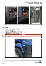
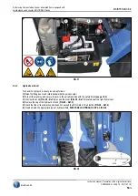
When handling the machine on public roads is required to lock the lift arm. The machine is equipped with two valves to interrupt the
flow of hydraulic oil to the cylinder of the lifting arm.
1) Retract the arm.
2) Move the attachment, if mounted on the universal attachment plate at a height of 20 cm from the ground.
3) Turn off the machine (see par. 8.3.6).
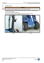
4) Close the two valves to block the lifting arm, placed in the vicinity of the lifting cylinder of the arm. The valves are closed when
the respective levers are perpendicular to the tube hydraulic oil.
5) Proceed to move on public roads.
To unlock the boom proceed as follows:
1) Turn off the machine (see par. 8.3.6).
2) Open the two valves to unlock the lift arm. The valves are open when the levers are parallel to the respective tube hydraulic oil.
8.3.4
Assembly of the attachment
DANGER
IT IS FORBIDDEN TO ASSEMBLY NON SUITABLE OR NON ORIGINAL ATTACHMENTS TO THE MACHINE.
WARNING
IT IS COMPULSORY TO READ THE MANUAL OF ATTACHMENT INSTRUCTIONS BEFORE PROCEEDING THE ASSEMBLY,
DISASSEMBLY AND USE OF THE ATTACHMENT.
WARNING
THERE ARE RESIDUAL RISKS N. 1, N. 2 AND N. 3 (SEE PAR. 3.2).
8.3.4.1 Mechanical attachment connection
To carry out the assembly of the attachment proceed as follows:
1) Make sure the attachment is positioned on firm and level ground.
2) Turn on the machine (see par. 8.3.2).
3) Push the multifunction joystick to the right in order to tilt forward the quick coupler.
4) Turn off the machine (see par. 8.3.6).
5) Get down from the machine and get the workplace D and E (see par. 4.2).
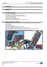
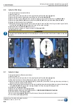
6) Lift and push back the two levers (FIG. 24 - Ref. 3) placed on the quick coupler, in order to raise the hook plugs.
7) Get on the machine again and turn it on (see par. 8.3.2).
8) Operating carefully draw up the quick coupler to one of the attachment so as to go up the upper round profile (FIG. 24 - Ref. 2)
in their curved seats of the attachment (FIG. 24 - Ref. 1).
9) Move slowly the multifunction joystick to the left, in this way the quick coupler leans backward, continue after lifting of a few
centimetres the quick coupler and automatically the coupling system closes allowing the two plugs to fit in the seats of the attachment
(FIG. 24 - Ref. 4).
10) Check visually the two levers (FIG. 24 - Ref. 5) are in low position. If not, it means the coupling was not successful.
11) Lift the attachment and lean forward moving the multifunction joystick to the right to check visually the two plugs of coupling are
correctly inserted in the fitted seats of the attachment. If not, relocate the attachment on the ground and repeat the procedure
from step 3).
Summary of Contents for 6 Series
Page 2: ......


