background image

23

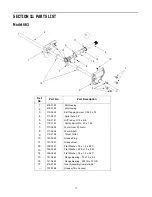
Model 663

IMPORTANT: For a proper working machine, use Factory
Approved Parts.
V-BELTS are specially designed to engage and disengage
safely. A substitute (non OEM) V-Belt can be dangerous by
not disengaging completely

Ref.

No.

Part No.

Part Description

1.

710-0599

Hex Washer Screw 1/4-20 x .50

2.

731-1324

Belt Cover

3.

732-0710

Extension Spring

4.

710-0627

Hex Screw 5/16-24 x .75

5.

710-3005

Hex Cap Screw 3/8-16 x 1.25

6.

05896A

Drive Clutch Idler Bracket

7.

748-0234

Shoulder Spacer

8.

756-0987

Pulley Half

9.

754-0346

V-Belt

10.

756-0986

Pulley Half

11.

736-0270

Bell Washer

12.

710-0230

Hex Cap Screw 1/4-28 x .50

13.

756-0313

Flat Idler

14.

710-1245

Lock Hex Cap Screw 5/16-24

15.

712-0181

Lock Jam Nut 3/8-16

16.

756-0569

Pulley Half

17.

736-0242

Bell Washer

18.

736-0505

Flat Washer

19.

754-0430

Belt

20.

756-0967

Auger Pulley

21.

736-0247

Flat Washer 3/8 x 1.25 OD

22.

736-0331

Bell Washer

23.

710-0696

Hex Cap Screw 3/8-24

24.

748-0360

Adapter Pulley

25.

710-0654A

Hex Screw 3/8-16 x 1.0

26.

629-0071

Extension Cord

27.

OEM-390-987

Electric Start Kit

Summary of Contents for E663G

Page 1: ...r state laws if any If a spark arrester is used it should be maintained in effective working order by the operator In the State of California the above is required by law Section 4442 of the California Public Resources Code Other states may have similar laws Federal laws apply on federal lands A spark arrester for the muffler is available through your nearest engine authorized service dealer or co...

Page 2: ... help from our Customer Support Department or an authorized dealer You can locate the model number by looking at the lower frame cover in the rear of your snow thrower A sample model plate is explained below For future reference please copy the model number and the serial number of the equipment in the space below CALLING CUSTOMER SUPPORT If you have difficulty assembling this product or have any ...

Page 3: ...come entangled in moving parts Wear footwear which will improve footing on slippery surfaces Before working with gasoline extinguish all cigarettes and other sources of ignition Check the fuel before starting the engine Gasoline is an extremely flammable fuel Do not fill the gasoline tank indoors while the engine is running or until engine has been allowed to cool at least two minutes Replace gaso...

Page 4: ...E AND STORAGE Check shear bolts engine mounting bolts etc at frequent intervals for proper tightness to be sure equipment is in safe working condition Never store the machine with fuel in the fuel tank inside a building where ignition sources are present such as hot water and space heaters clothes dryers and the like Allow engine to cool before storing in any enclosure Always refer to operators ma...

Page 5: ...ee Figure 2 and Figure 3 Look at the lower rear of snow thrower frame to be sure both cables are aligned with cable roller guides Secure the upper handle and lower handle with the two plastic wing knobs cupped washers and carriage bolt eyebolt on the left side previously removed See Figure 3 Figure 3 Adjust the eyebolt on the chute directional control so the rod does not come into contact with the...

Page 6: ... Use middle or high position when area to be cleared is uneven See Figure 5 Figure 5 IMPORTANT It is NOT recommended that this snow thrower be operated on a gravel surface as loose stones can be easily picked up and thrown by the machine If you must operate on a gravel surface ALWAYS adjust the skid shoes into the HIGH position to allow the shave plate maximum clearance Adjust skid shoes as follow...

Page 7: ...ge the wheel drive Release to stop This same lever also locks the auger control so you can turn the chute directional control without interrupting the snow throwing process If the auger control is engaged along with the traction control the operator can release the auger control on the left handle and the augers will remain engaged Release the traction control to stop both the augers and wheel dri...

Page 8: ...If your house wiring system is not a three wire grounded system do not use this electric starter under any conditions If your system is grounded and a three hole receptacle is not available at the point your starter will normally be used one should be installed by a licensed electrician When connecting the power cord always connect cord to starter on engine first then plug the other end into a thr...

Page 9: ... position To Engage Drive With the engine running near top speed move shift lever into one of the six FORWARD positions or two REVERSE positions Select a speed appropriate for the snow conditions that exist NOTE Use the slower speeds until you are familiar with the operation of the snow thrower Squeeze the traction control against the right handle and the snow thrower will move Release it and the ...

Page 10: ...x nuts Auger Control Adjustment Refer to the information found under the heading Final Adjustments in Section 3 of this manual to adjust the auger control Skid Shoe Adjustment The space between the shave plate and the ground can be adjusted by raising or lowering the skid shoes Refer to Skid Shoe Adjustment in Section 3 of this manual Traction Control Adjustment Refer to the information found unde...

Page 11: ...NT Make certain to check for correct adjustment of the shift rod as instructed under the heading Final Adjustments in Section 3 of this manual before operating the snow thrower Drive Wheels The wheels may be adjusted for two different methods of operation The adjustment is made by placing the click pins in one of two different holes on the right side of the unit See Figure 12 Figure 12 One Wheel D...

Page 12: ...st once a season Remove wheels clean and coat axles with a multi purpose automotive grease See Figure 13 Figure 13 Gear Shaft Lubricate the gear shaft with 6 n 1 grease at least once a season or after every 25 hours of operation available at auto parts stores or order part number 737 0170 Refer to Figure 10 IMPORTANT Keep all grease and oil off of the rubber friction wheel and aluminum drive plate...

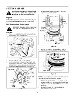
Page 13: ...ulley See Figure 17 Figure 17 Unhook the idler spring from the hex bolt on the auger housing See Figure 18 Figure 18 Back out the stop bolt until the support bracket rests on the upper auger pulley See Figure 19 Figure 19 NOTE Loosening the six nuts that connect the frame to the auger housing may aid in belt removal Lift the rear auger belt from the auger pulley and slip belt between the support b...

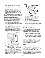
Page 14: ...e the friction wheel rubber from between the friction wheel plates See Figure 21 Reassemble new friction wheel rubber to the friction wheel plates and hub tightening the six screws in rotation and with equal force Position the friction wheel assembly up onto the pin of the shift rod assembly and slide the shaft through the assembly Reassemble in reverse order Shave Plate and Skid Shoes The shave p...

Page 15: ...or storage as instructed in the separate engine manual packed with your unit Remove all debris from the exterior of the engine and equipment Follow the lubrication recommendations found in Section 7 of this manual Always store the snow thrower in a clean dry area NOTE When storing any type of power equipment in an unventilated or metal storage shed care should be taken to rust proof the equipment ...

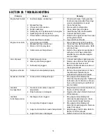
Page 16: ...ower 1 Spark plug wire loose 2 Gas cap vent hole plugged 3 Exhaust port plugged 1 Connect and tighten spark plug wire 2 Remove ice and snow from gas cap Be certain vent hole is clear 3 Refer to the Maintenance section of the engine manual Engine overheats 1 Carburetor not adjusted properly 1 Refer to the engine manual or have the carburetor adjusted by an authorized engine service dealer Excessive...

Page 17: ... tooth 8 717 0526 Worm Shaft 9 718 0186 Thrust Collar 10 721 0325 Grease Plug 11 721 0327 Grease Seal 12 736 0351 Flat Washer 76 x 1 5 x 030 13 736 0369 Flat Washer 508 x 1 0 x 020 14 736 0445 Flat Washer 76 x 1 5 x 060 15 741 0662 Flange Bearing 75 x 1 0 x 59 16 741 0663 Flange Bearing 503 ID x 75 OD 17 618 0122 Gear Assembly Complete 28 737 0168 Grease Two Ounces Model 663 2 12 4 6 7 10 9 14 11 ...

Page 18: ...5 6 4 7 7 8 9 10 11 12 1 5 13 14 15 16 17 18 1 19 20 21 22 23 24 25 25 26 28 29 26 1 1 30 31 32 33 34 8 35 Drive Clutch Cable Auger Clutch Cable Auger Clutch Cable Blower Housing 36 20 20 37 37 38 39 40 27 41 42 42 43 45 10 11 44 ...

Page 19: ...hift Bracket 19 784 5638 Frame Cover 20 710 0599 Hex Washer Screw 1 4 20 21 736 0351 Flat Washer 760 ID x 50 OD 22 717 1445 Gear 23 714 0126 Key 24 717 1444 7 Tooth Shaft 25 715 0249 Roll Pin 26 714 0143 Clik Pin 27 684 0042B Friction Wheel Assembly 28 656 0012A Friction Disc Wheel 29 684 0013B Wheel Shift Rod Assembly 30 746 0897 Drive Cable 31 748 0190 Spacer 32 684 0021 Friction Wheel Bracket A...

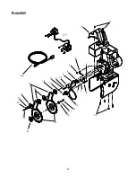
Page 20: ...20 Model 663 1 2 3 4 5 6 7 8 9 10 11 12 14 15 13 16 10 9 18 19 20 21 22 23 13 25 23 22 26 18 27 28 13 30 30 31 32 31 32 33 16 18 35 34 36 37 38 39 41 40 42 17 40 39 29 24 ...

Page 21: ...er 19 741 0475 Bushing 20 784 5647 Chute Crank Bracket 21 731 1379A Chute Adapter 22 712 0324 Hex Lock Nut 1 4 20 23 736 0463 Flat Washer 24 784 5618 Bearing Housing 25 710 0703 Carriage Screw 1 4 20 x 75 26 710 0604 Hex Washer Screw 5 16 18 27 736 0169 Lock Washer 3 8 28 712 0798 Hex Nut 3 8 16 29 741 0245 Hex Flange Bearing 30 784 5580 Skid Shoe 31 736 0242 Bell Washer 32 712 3010 Hex Nut 5 16 1...

Page 22: ...22 Model 663 1 2 3 4 5 6 7 4 8 9 10 11 12 13 15 14 16 17 18 19 20 16 16 21 22 23 24 25 26 27 ...

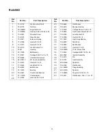
Page 23: ...05896A Drive Clutch Idler Bracket 7 748 0234 Shoulder Spacer 8 756 0987 Pulley Half 9 754 0346 V Belt 10 756 0986 Pulley Half 11 736 0270 Bell Washer 12 710 0230 Hex Cap Screw 1 4 28 x 50 13 756 0313 Flat Idler 14 710 1245 Lock Hex Cap Screw 5 16 24 15 712 0181 Lock Jam Nut 3 8 16 16 756 0569 Pulley Half 17 736 0242 Bell Washer 18 736 0505 Flat Washer 19 754 0430 Belt 20 756 0967 Auger Pulley 21 7...

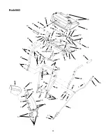
Page 24: ... 15 5 4 18 11 27 12 20 44 35 32 48 45 35 32 33 44 45 46 49 65 36 38 51 32 11 41 42 43 43 42 41 11 69 47 31 40 34 37 60 52 22 61 55 56 57 8 68 13 10 64 67 19 70 39 39 12 17 2 15 20 11 25 3 14 16 for ground wire 66 of light ass y 58 30 63 63 61 15 50 ...

Page 25: ... Tapping Screw 1 4 20 x 5 33 711 0653 Clevis Pin 34 712 0116 Jam Nut 3 8 24 35 714 0507 Cotter Pin 3 32 x 75 36 732 0145 Compression Spring 36 x 1 0 37 732 0193 Comp Spring 39 x 6 x 88 38 732 0746 Torsion Spring 44 x 8 39 735 0199A Rubber Bumper 40 736 0105 Bell Washer 401 x 87 x 063 41 736 0119 Lock Washer 5 16 42 736 0509 Special Washer 35 x 72 x 13 43 746 0778 Cable Z Fitting 44 747 0877 Cam Ro...

Page 26: ...26 ...

Page 27: ...27 ...

Page 28: ...ate manufacturer s warranty Please refer to the applicable manufacturer s warranty on these items b Routine maintenance items such as lubricants filters blade sharpening and tune ups or adjustments such as brake adjustments clutch adjustments or deck adjustments and normal deterioration of the exterior finish due to use or exposure c Log splitter pumps valves and cylinders have a sepa rate one yea...

Reviews: