


830-860 SERIES SELF-PROPELLED MOWERS
20
6.
Removing the variable speed pulley from the top
of the transmission:
NOTE:
New transmissions may or may not be
supplied with the variable speed pulley attached.
If it is necessary to transfer the pulley to the
replacement transmission, or if repair to the vari-
able speed pulley is necessary, use the following
directions as a guide.
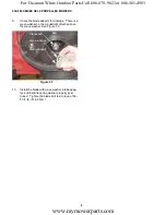
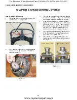
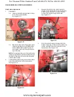
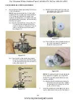
6a. Hold the input shaft from turning using a 7/
16” wrench while unscrewing the shoul-
dered nut using a 1-1/8” wrench. The nut
uses a conventional right-hand thread.
See Figure 6.15.
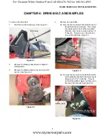
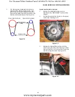
6b. The nut will be under slight spring tension.
Once the nut clears the end of the threads
on the input shaft, remove the nut and the
spring. See Figure 6.16.
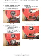
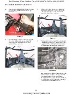
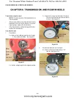
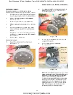
6c. With the nut and spring removed, the vari-
able speed pulley can be lifted off of the
input shaft. See Figure 6.17.
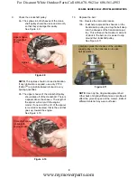
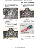
6d. The two sheaves of the variable speed pul-
ley can be separated for cleaning or
inspection. See Figure 6.18.
NOTE:
The splines should not need lubrication.
If any lubrication is applied, use a dry PTFE
(Teflon
TM
) or graphite based lubricant in very
sparing quantities.
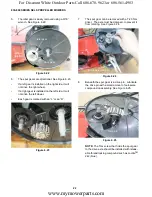
6e. Reassemble the variable speed pulley by
reversing the removal process. Tighten
the shoulder nut to a torque of 110-120
in.-lbs. (12.5-13.6 N-m).
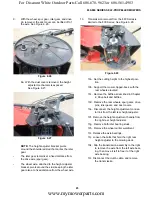
7.
Install the replacement transmission by revers-
ing the steps used to remove the transmission.
Figure 6.15
Figure 6.16
Lower sheave
Upper sheave
Spring
Shouldered nut
Figure 6.17
Figure 6.18
www.mymowerparts.com
For Discount White Outdoor Parts Call 606-678-9623 or 606-561-4983