830-860 SERIES SELF-PROPELLED MOWERS
17
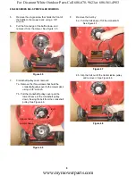
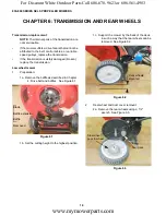
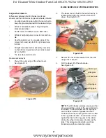
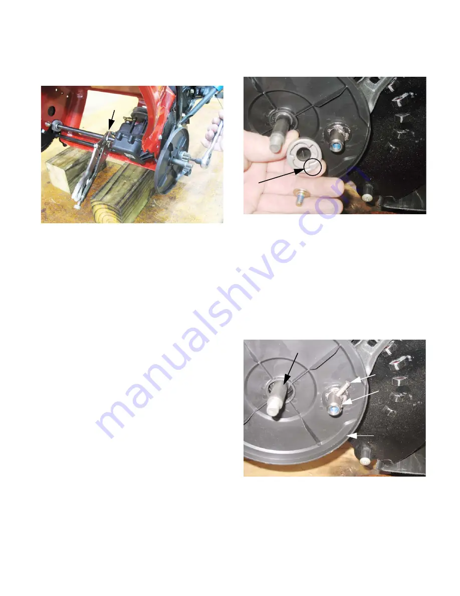
2b. Hold the rear drive axle to prevent it from
rotating, and remove the spur gears using
a T-20 Torx driver. See Figure 6.4.
NOTE:
The spur gears are side specific.
•
The one that goes on the left side is stamped
with and “L”, and the one that goes on the right
side is stamped with an “R”.
•
If they are mounted on the wrong sides, the
wheels will not drive.
NOTE:
The screws holding the spur gears to the
drive axle are both conventional right-hand
thread.
Figure 6.4
Clamp drive
axle
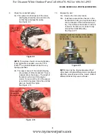
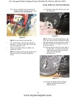
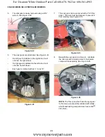
2c. Slip the spur gears off of the drive axle ends.
See Figure 6.5.
NOTE:
The Torx screw that holds the spur gear
to the drive axle should be installed with releas-
able thread locking compound such as Loctite
TM
242 (blue). Tighten it to a torque of 110-120 in.-
lb. (12.5-13.6 N-m)
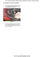
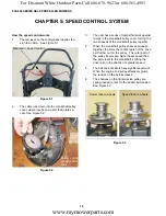
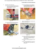
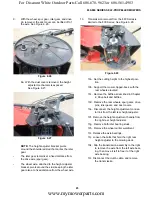
2d. Pull the drive pins out of the cross-holes in
the drive axle. The pins should be lubri-
cated with a small amount of anti-seize
compound on reassembly.
See Figure 6.6.
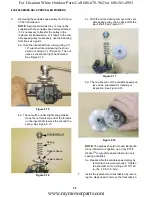
2e. Remove the plastic dust cover that fits
between the wheel and the height
adjuster bracket.
Figure 6.5
“L”
Figure 6.6
Dust cover
Drive pin
Drive axle
Axle that supports
the wheel
www.mymowerparts.com
For Discount White Outdoor Parts Call 606-678-9623 or 606-561-4983

